IR remote control circuit diagram
The here circuit is for a single channel Infrared remote controller which can be used to control home appliances and devices.
The IR remote controller consists of a receiver circuit similar to a latching switch circuit using IC 4017 and a transmitter circuit using a 555 IC.
IR Receiver circuit
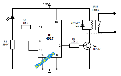
The receiver circuit is similar to a latching switch which ON and OFF the output alternatively for each triggering. Here the circuit arranged to toggle the output for each positive triggering at the clock input of the decade counter IC.
Refer: ON OFF Latching switch circuit using IC 4017
Whenever the infrared ray falls on the IR diode a voltage drop obtains across the resistor R1. It provides a positive edge at the clock input which toggles the output state. During each flash, the output just switches its previous state to an opposite present state. If the previous state was OFF then switches to ON else if it was an ON state then to OFF state.
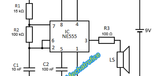
IR Remote circuit
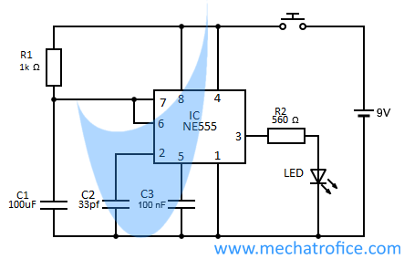
The IR remote consist of a one-shot pulse or monostable multivibrator using a 555 IC which have an ON-time period less than a second. An IR LED using a simple supply and a push-switch can act as an IR remote and it is enough to operate the receiver circuit as the circuit toggles only for the edge triggering. But the circuit is to flash the IR LED for only a fraction of a second to avoid false counting due to the motion of the hand or any improper passing, that might generate multiple pulses. Thus the circuit flashes only for a fraction of a second even for a prolonged press of push switch.
Components required
Receiver
IC1 – 4017
Resistor – R1 – 560, R2 – 10k, R3 – 1K
Transistor – Q1 – BC547
Diode – D1 – 1N4007
IR receiver diode
Relay – SPST 12V, 200ohms
Remote
IC1 -NE555
Resistor – R1 – 1k, R2 – 560
Capacitor- C1 – 100uf, C2 – 33pf, C3 – 100nf
Diode
IR LED
Push Switch
Sr
Pls help to I want control ir enable devices using galaxy j7prime mobile phone.
Give me any idea pls……..
Simply it’s not possible. Because for remote controlling the devices have an IR blaster, but in a j7 infrared sensor for IR blaster is not included with it.
How to make 4 channel IR
With this circuit, you can only make a sequential switching of 4 devices; one device operates at a time which repeats sequentially. Refer an HT12E encoder and HT12D decoder circuit to build 4 channel IR remote control.
To make a 4 channel IR remote control it is easy to build one with a microcontroller, it helps to eliminate a lot of circuit assembly.