Power supply failure indicator alarm circuit using NE555 IC
Here the circuit for a power failure indicator, which can be used along with any other device to detect a power outage.
The circuit uses an external 12V DC for checking the presence of a live supply. For AC 230V/110V supply lines, a 12V adapter is required to give the input feed.
The circuit consists of a 555 Astable multivibrator circuit. The output of the IC has connected to an LED and a buzzer which can provide a visual and audio indication. The circuit generates a low-frequency square wave which flashes the LED continuously and ON the buzzer with an interval, thereby generates a ” beep-beep” tone.
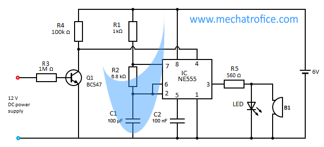 Here the transistor works as an inverter circuit. So when the Input DC line is present, the reset pin will have a low state input. And if there is no external supply the reset pin will have a high state input.
The 555 IC has an active low reset, thus the circuit will be interrupted when the input line is present. And during a power outage, the 555 starts to oscillate.
components required
IC1 – NE555
Resistor – R1 – 1k, R2 – 6.8k, R3 – 1M, R4 – 100k, R5 – 560
Capacitor – C1 – 100uF, C2 -100nF
Transistor – Q1- BC547
LED
B1- Buzzer
Supply 6V DC

Very nice ideas