Door opening alarm circuit diagram
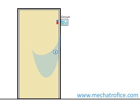
A door opening alarm circuit is an indicator or a security alert device which activates while opening the device attached door. And the alarm remains ON as long as the door is kept open.
For sensing the door position different types of methods can be used such as magnetic, light beam, mechanical, electrical etc. Most commonly used method is by using a reed switch which is simply a magnetic door alarm circuit.
Door opening alarm using reed switch
A Reed switch is an electrical switch activated by a magnetic field. It looks like a small tube-like device contains two ferrous material leads.
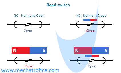
Reed switches are available with Normally Open (NO) and Normally Closed (NC) type. In a NO reed switch, the ferrous terminals inside the reed switch remain in an open position when there is no magnetic field. When any magnetic field comes near to the reed switch it closes the contacts and creates a conducting path. Whereas a normally closed switch works just in an opposite way.
The magnetic field is applied to the reed switch by a permanent magnet fixed on the door which is placed parallel to the reed switch. So a NO reed switch will close and open when the door close and open. Thereby the sensor circuit can determine the door position and control the alarm triggering.
Simple door open alarm circuit using transistor
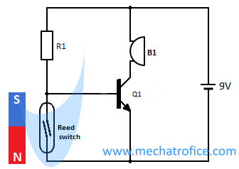
The above circuit is a simple switching circuit using a transistor. Here we are using a normally open reed switch. It is connected across the base-emitter of the NPN transistor. So when the door is close the reed switch Shorts the Base-emitter of the transistor which switches OFF the buzzer. So the alarm will remain in an OFF state as long as the magnet is placed close to the reed switch. When the door opens the magnetic field moves away and it opens the reed switch. Thus the short circuit across the base-emitters gets removed and the transistor switches to ON state which turns the buzzer ON.
Components required
NO Reed Switch
Q1 – BC547
Resistor – R1 – 1k
B1 – Buzzer
With a normally open reed switch, we have to invert the ON-OFF state of the switch so as to ON the buzzer when the switch is open and OFF when the switch is closed. If we are using a normally closed reed switch we can connect the buzzer directly through the reed switch. Because the switch close as the magnet moves away and open as it comes closer.
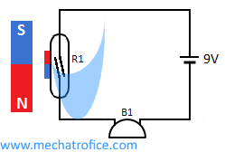
Normally reed switch can carry maximum current around 0.55 – 1.2A. So for low power devices, it can be used like a normal SPST switch.
Door alarm circuit diagram using IC 555
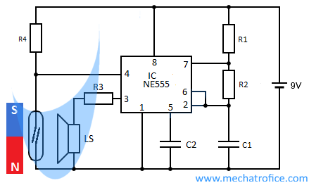
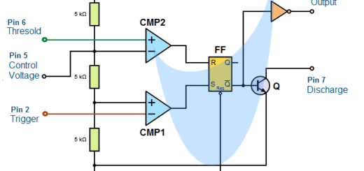
The circuit consists of a 555 tone generator circuit which is an astable multivibrator. The 555 IC has an active LOW state reset. When a LOW state input voltage is applied to the reset pin the operation of the 555 gets interrupted.
In the circuit, the reed switch is connected across the reset pin 4 of the 555 and the ground. When the door is close the reed switch grounds the pin4 and resets the 555 IC. The IC remains in a reset state and the tone generation will be OFF. When the magnet moves away the reset state of IC gets removed and the multivibrator starts the tone generation.
Components required
NO Reed Switch
IC – NE555
Resistor – R1 – 1k, R2 – 4.7k, R3 – 220, R4 – 1K
Capacitor – C1, C2 – 0.1uf
LS – Loudspeaker
Infrared door opening alarm
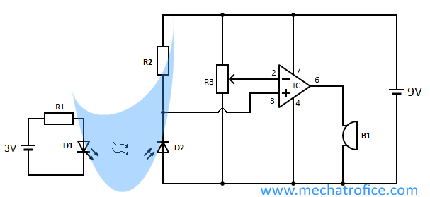
An IR door open alarm uses an IR LED and IR photodiode to detect the door position. The circuit consists of a comparator circuit using 741 op-amp IC. The buzzer gets ON when the voltage at the non-inverting pin 3 becomes greater than the inverting pin 2.
At a closed position, the IR rays from the LED directly falls on the photodiode and the voltage drop across it becomes very low approximately equal to zero. When the door is open the IR rays interrupts and the voltage across the inverting pin rise above the preset voltage at pin 2. Then the output at pin 6 switches to the high state and the alarm will activate.
Components required
NO Reed Switch
IC – 741
Resistor – R1 – 560, R2 – 1k, R3 -10K
Diode – D1 – IR photodiode, D2 – IR LED
B1 – Buzzer

Can I use my former 6 Volt Intercom for a Door Opened alert? Need Size of Bulbs an Socket- Wires are in place from former Intercom. Can I use a
Strobe light? Diagram to install and any suggestion and input will be appreciated. This is for my apartment.
Thankfully yours;
Fred Casaburi