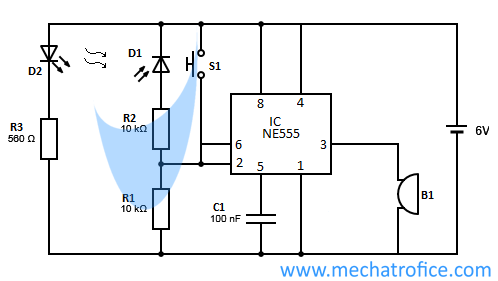
Infrared burglar alarm using IC 555 circuit diagram
This infrared burglar alarm can use at doors, entries, etc. To alerts us, when somebody crosses through the IR beam.
As the IR beams are invisible to human eyes, the circuit can work as a hidden security device.
To install the circuit. Place the IR LED and IR sensor on two opposite sides of a door or a passage. It should face each other, so as to fall the IR beam correctly on the IR sensor.
Under normal state, the IR beam always falls on the IR diode and the output state at pin 3 will remain in the low state. The IR beam will be interrupted whenever an opaque object crosses the beam. Once the Infrared beam breaks, the circuit triggers and the output switches to ON state. The output state remains until it resets by closing the Push switch ‘ S ‘. That is, the alarm remains ON, even the interrupt of the beam is removed. To prevent others from turning off the alarm, the reset switch or circuit should be placed far or hidden from the IR sensor. In the circuit an electronic Buzzer B1 is used to generate sound, which has an inbuilt tone, it can be substituted by another loud siren or bells depend on the use.
Infrared Burglar Alarm – Components required
IC – NE555
Resistor – R1,R2 – 10k, R3 – 560
Diode – D1 – IR receiver diode(IR photodiode), D2 – IR LED
Capacitor – C1-100nF
Switch- S1-push switch
B1-Buzzer
Supply 6v DC


what kind of IR led will span a doorway. part # ?
5mm IR LED of 890nm or 950nm, one with any similar rating.
i have radio shack 276-142 940mn . I will try. do you think i could replace the push button switch with a second set of IR LED’s and use this circuit to switch a motor on and off. the first set would turn on the motor (24v, 850ma.) at a low level and the second would turn off motor
at the high level. would I need a pair of NPN transistors to boost the out put of the NE555 pin #3
Yes, if you replace the switch with an IR LED it can turn OFF the circuit. Then the circuit turns ON in the absence of IR ray on D1 and turns OFF if the IR ray falls on the second IR LED.
The maximum output current of NE555 is 200 mA, but a high current really heats up the IC and damages it. So depending on the current required for the motor you can use the appropriate transistor.
THANK YOU.