Transformer less Capacitor DC power supply circuit and design
DC power supplies that use AC supply as inputs are usually sourced from distribution lines that have voltage ratings of 110V or 230V and frequency of 60 or 50Hz. A rectifier circuit converts this AC to DC but in order to obtain low voltage values like 3.3V, 6V, 9V, 12V, 24V, etc one of the voltage dropping methods has to be used.
A Step-down transformer is an easy and conventional method used in power supplies to convert a high voltage AC to low voltage values. Still, it is the most used method for very high voltage and high load current applications. But this method is not always suitable for small devices due to cost, size, and weight of transformer, power loss, etc.
Also, various compact and convenient methods are also available like SMPS, buck converters, switching circuits, etc to obtain a low voltage from a high voltage supply, but these types of circuits are a bit complex and costly.
This article briefly explains a simple and low-cost method to convert an AC line voltage to a low voltage DC power without a transformer by using a capacitor voltage dropper.
But this method also has few disadvantages like the limitation of the load current, not suitable for varying loads, safety issues, etc. This method is most suitable for small devices, LED light drivers, etc that require less current and always have a fixed load value.
So, when it comes to high current, compact, weightless, efficient, and stable regulated DC the best option is using an SMPS or other switching circuits.
Resistor voltage dropper
Before moving to the capacitor power supply just refer to this resistor voltage dropper for a better understanding of the voltage dropping method.
A resistor voltage dropper is a simple circuit that has a series resistor connected with the load to drop the voltage. This method can drop both AC and DC, so it can be used before or after rectification.
The voltage drop across a resistor is, V = IR. Here as the voltage is dropped by a purely resistive load, the active power consumed by the dropper resistor will be Vdrop x I or I2R.
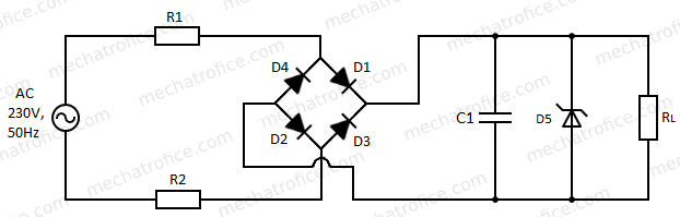
The given circuit is using a resistor voltage dropper where the resistor R1 is the key component that drops the majority of voltage. The value of R1 is calculated to drop voltage so as to obtain the required voltage across the load at a particular value of current. The circuit has a bridge rectifier circuit that converts the AC to DC followed by a capacitor filter circuit and a Zener voltage regulator.
Refer: Rectifier – Full wave bridge rectifier
DC Filter circuits – Capacitor filter circuit
Zener voltage regulator circuit
Example calculation
Consider a 12VDC, 50ma load that needs to be powered by a 230V,50HZ AC supply.
First, have to find the voltage that needs to be dropped, that is the difference between the supply voltage and the sum of all the voltage drop across the components including load.
Value of remaining components can be selected as,
R2 – 100Ω
D1,D2,D3,D4 – 1N4007
C1 = 1000μf
D5 = 12V, 1W
Load voltage = 12V, voltage across 100Ω resistor 0.05 x 100 = 5V
Also considering voltage drop of 1V (0.7 to 1.2V per diode) across two forward-biased diodes of a bridge rectifier, 1 x 2 = 2V.
Then the net voltage that needs to be dropped with R1 equals, 230 – 12 – 5 – 2 = 211V; since AC is in RMS voltage it is equal to the rectified RMS DC voltage.
So, the resistor required to drop a 211V with a current of 50mA.
Then the R = V/I = 211/50mA= 4220Ω
Let select 3.9K a resistor of standard value which is near to the calculated value. The resistor value is lower than the calculated value hence there will be a small quantity of extra current. If the resistor is selected above the calculated value then the current will be below the required value.
Now the voltage to be dropped with 3.9K and 100Ω resistors need to be calculated separately as the change in R1 changes the current and thereby voltage drop across R2. Voltage across R1 and R2, 230 – 12 – 2 = 216V.
The current value to drop 216V with 3.9K and 100Ω resistors = 216 / (3900 + 100) = 54mA.
Hence the load drives 50mA (load current for a 12V supply) and the remaining 4mA will be bypassed by the 12V Zener diode connected across the load.
The input 230V must not be a constant it can always fluctuate. So, in order to have a clearance to withstand the voltage fluctuation the resistor value R1 can be calculated by adding the minimum required Zener current with load current, i.e Vdrop/Iz + IL.
The input supply was 230V and the current drawn by the circuit is 54mA, then the input power = 230x54mA = 12.42W; considering the circuit as a pure resistive.
The output load power = 12x50ma = 0.6W
So, the power difference between input and output is 12.65 – 0.6 = 11.82W.
So, 11.82 watts of power is wasted by the circuit. The power loss by Zener and rectifier diodes are considerably lower value, also in any other switching circuits or capacitor dropper these losses can’t be eliminated. But here the major power loss is by the voltage dropping resistor, which is V x I = 11.37W.
So, using a resistor voltage dropper is not an efficient method as it has a high amount of power loss as heat.
Capacitor voltage dropper
Now a capacitor can be used in AC circuits to drop the voltage using capacitive reactance instead of using a resistive component. Here just need to find the value of a capacitor that can drop a voltage equivalent as the resistor do; the rest of the calculations were completed in the above portion of the resistance dropper.
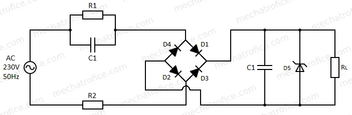
Taking the example for a 12V, 50mA load with 230V,50Hz AC supply using same above circuit by replacing the resistor with a capacitor. So, the resistance required to drop the voltage is 4220Ω, so a capacitor with a reactance value almost near 4220Ω needs to be calculated.
The circuit has a Bleed resistor connected parallel to the capacitor which is used to discharge the current. It can be a high-value resistor of 470k – 1M, so in the below calculations R1 is neglected as the resultant resistance across the capacitor will be almost the same as the value of capacitive reactance.
The capacitive reactance can be calculated as, Xc = 1/2nfC, it is the property of the capacitor to oppose the AC which is inversely proportional to the supply frequency and value of capacitance.
Xc = 4220Ω = 1/ 2πfC
F = 50Hz
C = 1/ 4220 x 2 x π x 50 = 0.754μf
As the capacitive reactance is inversely proportional to the value of capacitance, the selected standard value of the capacitor needs to be above the calculated value to get more current.
So, if we choose a capacitor of 1μf it can offer capacitive reactance of 3183.1Ω
Same as resistance dropper (refer), the current value to drop 216V with 3183.1Ω capacitive reactance with 1μf capacitor and 100Ω resistors = 216 / Z
The resistor dropper circuit is purely resistive, but here circuit has a reactive component which is capacitive reactance. Pure capacitive and Resistive loads are 90 degrees out of phase and capacitive circuit has a leading power factor; current leads voltage.
The resultant impedance, Z = √ Xc2 + R2 = 3184.67Ω; Xc = 3183.1Ω & R = 100Ω.
Then the current becomes 216/3184.67 = 67mA in which 50mA load current and Zener current Iz = 17mA.
So, the input power of the circuit is calculated as apparent power, as it has both active and reactive power. Apparent power = VI = 230 x 0.067 = 15.41W.
The power of capacitor = I2 x XL sin 90 = (0.067)2 x 3183.1 = 14.28VAR
The output load power = 12V x 50ma = 0.6W
Unlike a resistive dropper which consumes active power, here the majority of power in the circuit is reactive. Hence using a capacitor voltage dropper is far efficient than using a resistive dropper.
Both capacitive and resistive dropper circuits have many disadvantages also. The circuit has no electrical isolation between the AC line and the DC output, which can cause shock or other electrical accidents. It is practically useful for low current devices only and not feasible for large loads as high capacitance is required for high current, but increasing the value of capacitor makes the circuit bulkier.
It is not efficient with varying loads because the same amount of power will be consumed by the circuit because the current needs to flow always so as to drop voltage across the capacitor.
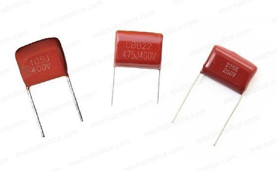
- Only polyester X-rated capacitors should be used for this circuit and make sure it has an appropriate voltage rating.
- Never test the circuit in open load condition without connecting Zener or a resistive load. If the circuit is connected only with a filtering capacitor then the voltage across it will become extremely high.
- The circuit has live AC points that might cause electric shock, so never work with live input supply. Only test this type of circuit with the supervision of a professional or with proper precautions at your own risk.