Timer switch with Relay and LCD Arduino code
A timer switch is an electrical switch that is operated by means of a timer circuit or timer mechanism that measures specific time intervals. It can be used to switch ON or OFF a device after a particular period of time set by the user.
In the below circuit, the output of the Arduino is connected to a relay module that can be used to ON or OFF appliances connected to an external supply like an AC power source, battery supply, etc.
Arduino Switch OFF Timer
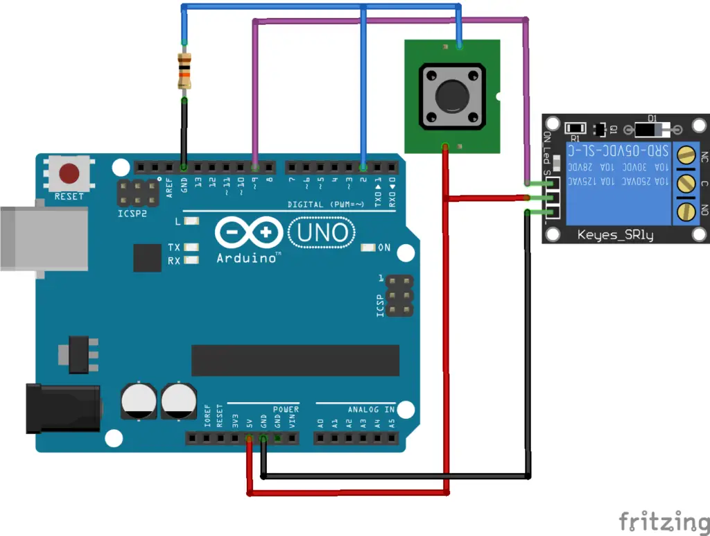
This is a basic program to switch off the device after a particular time period since it is switched ON. When we power on the circuit the output pin 9 will be in a low state by default. Hence the Load connected to the relay will remain OFF. In the circuit a push-button is connected to pin2, it is the ON button to turn ON the output. Once it is pressed the output at pin 9 switches to a high state, the relay energizes and the relay contacts switch to NO terminal which switches ON the load or appliances connected to it.
Here in the code, the off-time is initialized as 1 minute; the time value used in the code is in minutes. Once it is turned ON, the device will be turned off after the time specified in the variable “offtime”.
Code
const int switch_on = 2, output = 9;
int offtime = 1, off_timer_start = 0;
void setup() {
  pinMode(switch_on, INPUT);
  pinMode(output, OUTPUT);
}

void loop() {
  int x = ((millis() / 1000) - off_timer_start) / 60;
  if (digitalRead(switch_on) == HIGH) {
    off_timer_start = (millis() / 1000);
    digitalWrite(output, HIGH);
  } else if (x >= offtime && digitalRead(output == HIGH)) {
    digitalWrite(output, LOW);
  }
  delay(1000);
}
Switch OFF timer with time adjust and LCD display
This code is the same as above, but with a few additional options to change the off time, LCD display to show the off time, the present state of the device, and remaining time to OFF.
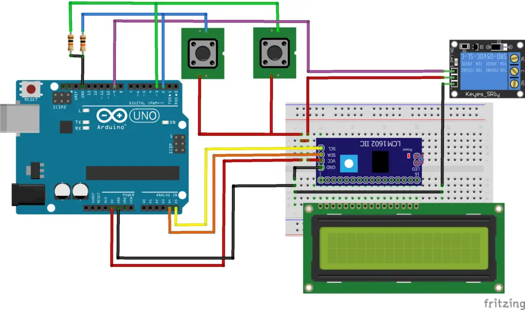
Here the circuit has two input button switches, one is connected to Pin 2 which is to switch ON the device, and the second button is connected to pin3 to set the OFF-time value; in the above code the off time needs to be declared at first and once the sketch is uploaded then it needs to re-upload again to change the off-time value. Here that disadvantage can be overcome by adding input to change the OFF time.
In the code as long as the pin3 is held ON, the off-time increments by 1 and repeats again from 0 once it reaches the value of 30 minutes. The limit of time, increment value, speed of increment can be modified by adjusting the values in the code; it is specified in the corresponding lines in the code.
Code
#include <LiquidCrystal_I2C.h>
LiquidCrystal_I2C lcd(0x27, 16, 2);
uint8_t clock[8] = {0x0, 0xe, 0x15, 0x17, 0x11, 0xe, 0x0};
const int switch_on = 2, input_off_time = 3, output = 9;
int off_timer_start = 0, offtime = 0;
void setup() {
  pinMode(switch_on, INPUT);
  pinMode(input_off_time, INPUT);
  pinMode(output, OUTPUT);
  lcd.init();
  lcd.backlight();
  lcd.setCursor(6, 0);
  lcd.print("OFF       ");
  lcd.createChar(2, clock);
  lcd.setCursor(0, 1);
  lcd.write(2);
  lcd.print((String)" " + offtime + " ");
}

void loop() {
  int x = ((millis() / 1000) - off_timer_start)/60;
  if (x <= offtime && digitalRead(output) == HIGH) {
    int m = ((offtime * 60) + off_timer_start - (millis() / 1000))/60;
    int s = ((offtime * 60) + off_timer_start - (millis() / 1000))%60;
    lcd.setCursor(10, 0);
    lcd.print((String)" " + m + ":" + s +" ");
  }
  if (digitalRead(switch_on) == HIGH) {
    digitalWrite(output, HIGH);
    off_timer_start = millis() / 1000;
    lcd.setCursor(6, 0);
    lcd.print("ON        ");
  } else if (x >= offtime && digitalRead(output == HIGH)) {
    digitalWrite(output, LOW);
    lcd.setCursor(6, 0);
    lcd.print("OFF       ");
  }
  while (digitalRead(input_off_time) == HIGH) {
    if (offtime <= 29) { //change max time limit
      offtime += 1; //change increment by x
    } else {
      offtime = 0;
    }
    lcd.setCursor(0, 1);
    lcd.write(2);
    lcd.print((String)" " + offtime + " ");
    delay(500);// adjust speed of incrementing
  }
}
Arduino ON and OFF timer
This is an expanded version of the above program, here we have additional options to set time to both ON and OFF the device. Here the device is ON after the time set to “ontime” and OFF after the “offtime”.
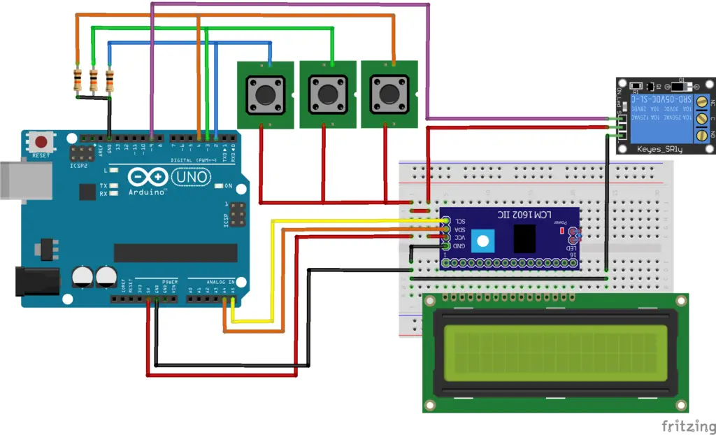 Here the switch connected to pin3 can be used to change on time and pin4 to change the off time. The pin2 is the same as above to turn ON the device.
#include <LiquidCrystal_I2C.h>
LiquidCrystal_I2C lcd(0x27, 16, 2);
uint8_t clock[8] = {0x0, 0xe, 0x15, 0x17, 0x11, 0xe, 0x0};
const int switch_on = 2, input_on_time = 3, input_off_time = 4, output = 9;
int timer_start = 0, ontime = 0, offtime = 0;
String device_status = "OFF";
void setup() {
  pinMode(input_on_time, INPUT);
  pinMode(input_off_time, INPUT);
  pinMode(output, OUTPUT);
  lcd.init();
  lcd.backlight();
  lcd.createChar(2, clock);
  lcd.setCursor(8, 1);
  lcd.write(2);
  lcd.print((String)" OFF" + offtime + " ");
  lcd.setCursor(0, 1);
  lcd.write(2);
  lcd.print((String)" ON" + ontime + " ");
  lcd.setCursor(6, 0);
  lcd.print("OFF       ");
}

void loop() {
  int x = ((millis() / 1000) - timer_start)/60;
  if (x <= ontime && device_status == "TO_ON") {
    int m = ((ontime*60) + timer_start - (millis() / 1000))/60;
    int s = ((ontime*60) + timer_start - (millis() / 1000))%60;
    lcd.setCursor(10, 0);
    lcd.print((String)" " + m + ":" + s + " ");
  } else if (x - ontime <= offtime && device_status == "TO_OFF") {
    int m = ((offtime*60) + timer_start + (ontime*60) - (millis() / 1000))/60;
    int s = ((offtime*60) + timer_start + (ontime*60) - (millis() / 1000))%60;
    lcd.setCursor(10, 0);
    lcd.print((String)" " + m + ":" + s + " ");
  }
  if (digitalRead(switch_on) == HIGH) {
    timer_start = millis() / 1000;
    device_status = "TO_ON";
  }
  else if (x - ontime >= offtime  && device_status == "TO_OFF") {
    digitalWrite(output, LOW);
    lcd.setCursor(6, 0);
    lcd.print("OFF       ");
    device_status = "OFF";
  } else if (x >= ontime && device_status == "TO_ON") {
    digitalWrite(output, HIGH);
    lcd.setCursor(6, 0);
    lcd.print("ON        ");
    device_status = "TO_OFF";
  }
  while (digitalRead(input_on_time) == HIGH) {
    if (ontime <= 24) {
      ontime += 1;
    } else {
      ontime = 0;
    }
    lcd.setCursor(0, 1);
    lcd.write(2);
    lcd.print((String)" ON" + ontime + " ");
    delay(500);
  }
  while (digitalRead(input_off_time) == HIGH) {
    if (offtime <= 24) {
      offtime += 1;
    } else {
      offtime = 0;
    }
    lcd.setCursor(8, 1);
    lcd.write(2);
    lcd.print((String)" OFF" + offtime + " ");
    delay(500);
  }
}
Hello
can you help me to show how to add EEPROM in sketch “Switch OFF timer with time adjust and LCD display” so when power outage happen and on again we not need to set the timer again.
Try this code for EEPROM time backup. Once the time is set after the first sketch upload, the last timer value will be stored in the EEPROM memory (using EEPROM.write inside the while loop) and it will read every time when the program starts running (using the EEPROM.read function inside void setup()).
#include <LiquidCrystal_I2C.h> #include <EEPROM.h> LiquidCrystal_I2C lcd(0x27, 16, 2); uint8_t clock[8] = {0x0, 0xe, 0x15, 0x17, 0x11, 0xe, 0x0}; const int switch_on = 2, input_off_time = 3, output = 13; int off_timer_start = 0, offtime = 0, address = 0; void setup() { pinMode(switch_on, INPUT); pinMode(input_off_time, INPUT); pinMode(output, OUTPUT); lcd.init(); lcd.backlight(); lcd.setCursor(6, 0); lcd.print("OFF"); lcd.createChar(2, clock); lcd.setCursor(0, 1); lcd.write(2); offtime = EEPROM.read(address);// Read value stored in eeprom address '0'. lcd.print((String)" " + offtime + " "); } void loop() { int x = ((millis() / 1000) - off_timer_start) / 60; if (x <= offtime && digitalRead(output) == HIGH) { int m = ((offtime * 60) + off_timer_start - (millis() / 1000)) / 60; int s = ((offtime * 60) + off_timer_start - (millis() / 1000)) % 60; lcd.setCursor(10, 0); lcd.print((String)" " + m + ":" + s + " "); } if (digitalRead(switch_on) == HIGH) { digitalWrite(output, HIGH); off_timer_start = millis() / 1000; lcd.setCursor(6, 0); lcd.print("ON "); } else if (x >= offtime && digitalRead(output == HIGH)) { digitalWrite(output, LOW); lcd.setCursor(6, 0); lcd.print("OFF "); } while (digitalRead(input_off_time) == HIGH) { if (offtime <= 29) { //change max time limit offtime += 1; //change increment by x } else { offtime = 0; } lcd.setCursor(0, 1); lcd.write(2); lcd.print((String)" " + offtime + " "); EEPROM.write(address, offtime);// Stores the time off value in eeprom address '0'. delay(500);// adjust speed of incrementing } }it work flawlessly many thanks 🙂
one last question which part i need to remove if i want this code working right after turn on without press the switch_on button?
i already change the if (digitalRead(switch_on) == HIGH) { with if (x <= offtime )
but its not working.
Then i made slight change with the code.
void loop() {
unsigned long currentTime = (millis() / 1000) / 60;
if (currentTime <= offtime && digitalRead(output) == HIGH) {
int m = ((offtime * 60) + off_timer_start – (millis() / 1000)) / 60;
int s = ((offtime * 60) + off_timer_start – (millis() / 1000)) % 60;
lcd.setCursor(10, 0);
lcd.print((String)" " + m + ":" + s + " ");
}
if (currentTime = offtime && digitalRead(output == HIGH)) {
digitalWrite(output, LOW);
lcd.setCursor(7, 0);
lcd.print(“OFF “);
}
while (digitalRead(input_off_time) == HIGH) {
if (offtime <= 60) { //change max time limit
offtime += 1; //change increment by x
} else {
offtime = 0;
}
lcd.setCursor(9, 1);
lcd.write(2);
lcd.print((String)" " + offtime + " ");
EEPROM.write(address, offtime);// Stores the time off value in eeprom address '0'.
delay(500);// adjust speed of incrementing
}
}
with this change the result is:
– the countdown still not working
– the timer relay work but 1 minute later. i mean if i set 1min the relay will of after 2min
can u help me again? im sorry if i ask to much and for my bad english.
thanks for your answer
You are always welcome and feel free to ask any questions. Try this,
If you need to ON the output right after turning ON add “digitalWrite(output, HIGH)” inside void setup, so the output becomes high as soon as the power is ON. The countdown works only if the output is HIGH. Also to turn OFF the if condition should be like this “if (x >= offtime && digitalRead(output == HIGH))”.
Hello!
It’s very late for me to ask for help for this project. But anyway, can you help me make the ”SWITCH_ON” button to PAUSE and START the Timer again?
Thanks you.
You can refer to this stopwatch project, http://mechatrofice.com/arduino/arduino-stopwatch-with-lcd-display. It includes functions for START, STOP, PAUSE, and RESUME actions.
lol what a simple solution but missed 😀
its working like i want now the countdown work the timer work everything work
many thanks for your help
You are welcome. 🙂
Hello, plxx help i am using three leds 1 2 3 whever i push the button led 1 and 2 glow and after 6 seconds the led 2 off and led 3 and one remains On… And than whenever i push the button again all led gone off … And again the process start from beginning when i press the button…Need code plxxx
Try this code,
//All variables like state, LEDstate need to intialised as integer with value 0. Assign pin number to LED1, LED2 & LED3.
if (state == 0 && digitalRead(Switch) == HIGH) {
state = 1;
LEDstate=!LEDstate;
}
if (state == 1 && digitalRead(Switch) == LOW) {
state = 0;
}
if(LEDstate == HIGH){
digitalWrite(LED1,HIGH);
digitalWrite(LED2,HIGH);
delay(6000);
digitalWrite(LED2,LOW);
digitalWrite(LED3,HIGH);
} else if(LEDstate == LOW){
digitalWrite(LED1,LOW);
digitalWrite(LED3,LOW);
}
Refer toggle switch action: http://mechatrofice.com/arduino/toggle-switch
Hello, great tutorial. Can I ask if want to turn on a lamp(LED) and set the timer using button for simulation in proteus, can I use the same code? If not can you show an example please
Yes, you can use this same code with proteus by using exact circuit connections.
can you help me ? how do i get right coding to a dual output for relay timer ? my project is switch on the switch and after 5 hours it will turn off . im lost
Use the first code which is given for Arduino Switch OFF Timer.
Set int offtime = 300, that is 5hours * 60 = 300minutes. Then, once you press the switch at pin 2, the output at pin 9 switches high and OFF after 5 hours.
many thanks for the info…excellent..
Is there anyway to use 0.96 oled instead of above mentioned display?
Yes, you can use 0.96 OLED instead of LCD.
OLED has an I2C communication protocol, so it is easy to replace the connections of SCL and SDA pins of the LCD I2C module with that of the OLED display. Similarly in the code also, You just have to replace the LCD functions with OLED functions.
Refer OLED Arduino guide : https://create.arduino.cc/projecthub/Arnov_Sharma_makes/0-96-inch-oled-getting-started-guide-78163a
So i have one more doubt. The relay module i got have octocouplers. So what changes i need to make on the advanced version of your project?
The majority of the relay modules have optocouplers, you have to do nothing additional in this circuit. Just connect the relay module signal input to the digital output pin of the Arduino as shown in the existing circuit.
hi! my name is anne. i really admire your work. Can you help me modified the code in Arduino Switch OFF Timer, when i tried it, the relay is already on at the beginning and when i push the button, the relay will turn off for about 1 minute, right? however, i need the exact opposite of it, like when i connect the power supply, the initial state of relay must be off, and when i press the button, it will turn on for about 5 minutes, after that it will automatically off. i badly need this one, i hope you’ll see my comment.
Relay modules can be active high or active low. An active low functions if the input signal is low and an active high functions if the input is high.
Your relay is currently in an active-low configuration that’s why it is ON at the beginning and OFF for a fixed period of time.
The code given is the same for your requirement, what you have to do is change your relay mode from active LOW to HIGH(If the module has a jumper to change) or replace all the digitalWrite(output, HIGH/LOW); in the code with just opposite; if it is a high then change to low and if low then to high; so it will function just the opposite.
wow thank you for the reply! it’s working now, i can’t believe it LOL. thanks for the help
Som nováčik. Môžem sa opýtať ako sa dá urobiť časovač jedným tlačidlom že sa prelínajú LED. Myslím to tak že stlačím tlačítko a keď LED červená sa zapne na 1h a ak by som znova stlačil tlačítko zelená LED sa zapne na 2h a červená LED sa vypne. Ďakujem za pomoc
Which part of the code would I need to change to make it go up in 5 minute increments?
change the line
offtime += 1; //change increment by x
to
offtime += 5; //change increment by x
Hello
Can you help me how to add 4 timer in Arduino code with the same buttons
Could you explain your requirement in detail?
Hi can you show me the diagram of two air conditioner with 8 hours timer duration using arduino
hello sir, great tutorial.
can you help me a bit? I’m currently doing some automation project for auto refilling coolant at a machine. I’m using a float switch to give an on/off signal for my relay. My question is how to get the right coding as I want it to off whether by the timer or the float switch itself?
You can use the float switch itself until it has an operation to run for a set time.
Hello! I have some problems with the Switch Off Timer. Whenever I press the button to start the lamp and begin the countdown the Arduino restarts and resets the program, I have tried switching several of the parts for new ones including the Arduino.
Thx beforehand! //ANX
What power source are you using? Is your power supply rated high enough to power the LCD and the total circuit?
Hi, nice project! 🙂 I have a question: is it possible that if the Arduino detects if there is a 24Vdc (via a voltage divider at one of the available UNO inputs) that at that point a countdown timer starts (adjustable between 0 and 10seconds) and at the end of the countdown time a Relay is set active by the Arduino… (And the Relay is NOT Active (anymore) when the 24Vdc Voltage source is 0V or disconnected). Can you help me with this question and/or do you need more info?
Thank you.
Anton.
Yes, it’s possible to achieve this with an Arduino. You can use the analog input to detect the 24V signal using a voltage divider, then start a countdown timer. When the timer reaches the set duration, activate a relay or continuously monitor the voltage and reset the timer when the voltage drops to 0V or disconnects.
Hi there. I was searching for a timer that would work my microwave kiln. This looks ideal but just to clarify. After the circuit cycles from the on state and to the off state, can you set how many times it loops the off on state e.g 7 minutes on 1 minute off x 4 . And is it possible to go further and do 7,1 x4 then 4,2 x2 or would that be too detailed?
Regards Aiden and thank you in advance
Dear Admin, why is my question (I Replied yesterday) not placed but disappeared?
Was there something wrong with my question, please let me know.
Thank you.
Anton
Dear admin, what if I want to make the on/off timer repeat continuously? please help, thank you