Arduino Ammeter – How to Measure DC Current using Arduino?
An ammeter is an instrument used to measure current flow in a circuit, which is measured in amperes. In a Digital ammeter, we measure the voltage across a shunt resistance, which is series to the load; hence the current through the Load and shunt resistor is the same. An ammeter is connected in series with the load whereas a voltmeter is connected across the load. Because the current through the circuit is always the same in series and voltage the same in parallel.
A shunt resistor should have very low resistance, that is it should not drop any considerable amount of voltage. Because the actual load current varies if an additional resistance is added in series.
Arduino Ammeter using Serial Monitor Display
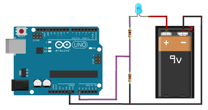 In the Arduino DC ammeter circuit, the analog input A0 and GND are connected across the two terminals of the shunt resistor R. By taking the voltage difference between the input A0 and GND we can obtain the voltage across the resistance R. From the value of voltage measured across the shunt resistance, we calculate the current through the circuit by applying Ohms Law, The voltage drop across Resistor, V = I R Then the current, I = V/R Then the current through the circuit is equal to the voltage across the shunt resistor divided by the known shunt resistance value. Code – Serial Display
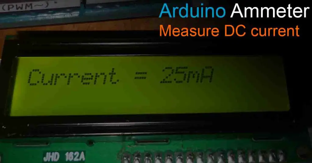
float Vacross,Iamp = 0;
const int Shunt_Res = 100;

void setup() {
  Serial.begin(9600);
}

void loop() {
  Vacross = analogRead(A0);

  Vacross = (Vacross * 5.0) / 1023.0;
  Iamp = (Vacross * 1000) / Shunt_Res;

  Serial.print("Current = ");
  Serial.print(Iamp);
  Serial.println("mA");
  delay(1000);
}
Ammeter using LCD Display
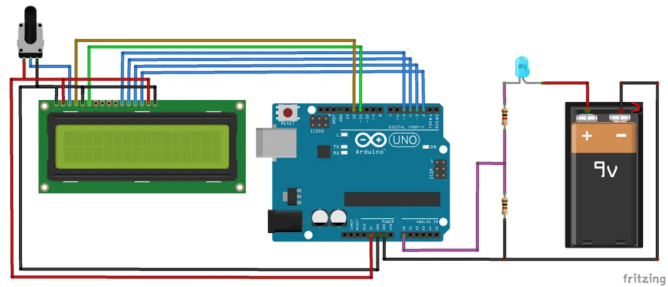 In the circuit, it is shown that how a current through an LED is Measuring using Arduino DC ammeter. The LED, 100Ω shunt resistor and a 1kΩ resistor are in series, thus the current through them is always the same value. Then it can be calculated that the current through the LED is the voltage drop across the 100Ω shunt resistance divided by shunt resistance value 100. I = Vacross / 100 Code – LCD Display
#include <LiquidCrystal.h>
float Vacross,Iamp = 0;
const int Shunt_Res = 100;
LiquidCrystal lcd(12, 11, 5, 4, 3, 2);

void setup() {
  lcd.begin(16, 2);
}

void loop() {
  Vacross = analogRead(A0);

  Vacross = (Vacross * 5.0) / 1023.0;
  Iamp = (Vacross * 1000) / Shunt_Res;

  lcd.setCursor(8, 0);
  lcd.print("Current = ");
  lcd.print(Iamp);
  lcd.print("mA");
  delay(1000);
}
The resolution of the measured value of the current can be adjusted by varying the value of the shunt resistor. For measuring loads with low resistance that is a high current, the value of the shunt resistor can be selected low. And if the load resistance is high means a small amount of current, then a shunt resistor of higher resistance is required so as to obtain a minimum voltage drop for measuring. By adjusting this measuring range the instrument can measure current in wide ampere ranges. The maximum input voltage of the Arduino pin is 5V. It should be considered that the voltage drops across the analog input pin never rise above 5V.
In the above circuits, you can find that the voltage across the analog input A0 and GND will be always below 5V for an external supply of 9V. Because voltage value greater than 4V definitely drops across the 1kΩ resistor and the LED. Hence no voltage drops across the A0 with above 5V. For safety, an additional 5V Zener diode can be added across the resistor to bypass any voltage above 5V. Even though it is not recommended to drop a voltage of 5V across the shunt because the drop across it should be always as low as possible. That is, it is not contributing any resistance or voltage drop to the circuit. Also, consider the power rating of the resistor that the circuit current is not exceeding its maximum current rating.
you mentioned shunt resistor is 100 Ohms but in code it is 1000, why is that?
The shunt resistor value has now been changed. Use the shunt resistor value the same as the value used in the circuit; the value of the resistor connected between A0 and GND.