RF remote control using Arduino and 433mhz ASK module
An RF remote controller is a device that can be used to switch ON/OFF equipment or devices wirelessly using radio frequency transmission. The remote or transmitter part is a handheld device that has switches or other input options to select the operation. At the receiver side, it executes the operation like switch ON/OFF as per the data of transmitted signal.
RF remotes are an efficient and good choice for various remote-control applications like ON/OFF lights, fans, other electrical appliances, etc. Compared to infrared remote controls RF remotes have a longer operating range and even it doesn’t need a line of sight between the transmitter and the receiver.
In the here circuit a 433Mhz ASK module is using for RF transmission. Refer to the ASK module interface with Arduino using Radiohead library.
Single device RF remote control
Transmitter
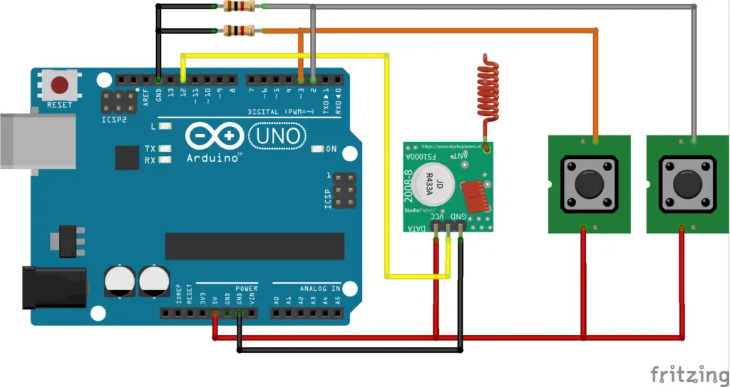
Remote transmitter circuit – figure 1
The transmitter circuit has two switches, one is an ON switch and the other is an OFF switch. The transmitter sends the string “Switch_ON” and “Switch_OFF” on pressing the ON and OFF switches respectively.
Transmitter code
#include <RH_ASK.h>
#include <SPI.h>

const int switch_on = 2, switch_off = 3 ;
int state = 0;
char *msg;
RH_ASK driver;

void setup()
{
  driver.init();
  pinMode(switch_on, INPUT);
  pinMode(switch_off, INPUT);
}

void loop()
{
  if (digitalRead(switch_on) == HIGH) {
    msg = "Switch_ON";
    state = 1;
  }
  else if (digitalRead(switch_off) == HIGH) {
    msg = "Switch_OFF";
    state = 1;
  }
  else if (state == 1) {
    driver.send((uint8_t *)msg, strlen(msg));
    driver.waitPacketSent();
    delay(200);
    state = 0;
  }
}
Receiver
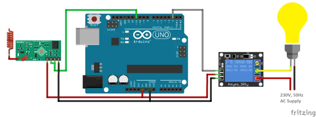
Remote control receiver circuit – figure 2
The receiver compares whether the received string matches with any of the comparison strings and then either switch the digital output to HIGH or LOW state with respect to the received string; Switches to HIGH state if the received string is “Switch_ON” or to LOW state if it is “Switch_OFF”.
Receiver code
#include <RH_ASK.h>
#include <SPI.h>

RH_ASK driver;
const int output = 2;
char receive[32];

void setup()
{
  driver.init();
  pinMode(output, OUTPUT);
}

void loop()
{
  uint8_t buf[RH_ASK_MAX_MESSAGE_LEN];
  uint8_t buflen = sizeof(buf);

  if (driver.recv(buf, &buflen))
  {
    memset(receive, 0, sizeof(receive));
    for (int i = 0; i < buflen; i++) {
      receive[i] = buf[i];
    }
    if (strcmp(receive, "Switch_ON") == 0) {
      digitalWrite(output, HIGH);
    } else if (strcmp(receive, "Switch_OFF") == 0) {
      digitalWrite(output, LOW);
    }
  }
}
The digital output at the receiver is connected to a relay module that can be used to drive any loads with external supplies.
Ensure the relay ratings such as coil resistance, load current, operating voltage, etc are safe with the Arduino I/O current, load current, etc.
To make the device compact and handy, the same circuit and pin connection can be used with smaller boards like Arduino nano, pro mini, etc.
Additional codes
Single device control with latching switch
The above circuit has two separates switches to turn ON and OFF the device. Here a single switch is used as a latching switch that can ON and OFF the output for alternate switch pressing.
Transmitter
figure – 3
#include <RH_ASK.h>
#include <SPI.h>

const int switch_in = 3;
int state = 0;
char *msg;
RH_ASK driver;

void setup()
{
  driver.init();
  pinMode(switch_in, INPUT);
}

void loop()
{
  if (digitalRead(switch_in) == HIGH && state == 1) {
    msg = "Switch";
    driver.send((uint8_t *)msg, strlen(msg));
    driver.waitPacketSent();
    delay(200);
    state = 0;
  }
  else if (digitalRead(switch_in) == LOW) {
    state = 1;
  }
}
Each time the transmitter sends the same text “switch”, the receiver toggles the output for each time when it receives the string “Switch”.
Receiver
Refer figure 2 for circuit.
#include <RH_ASK.h>
#include <SPI.h>

RH_ASK driver;
const int output = 2;
char receive[32];
int output_state = 0;
void setup()
{
  driver.init();
  pinMode(output, OUTPUT);
}

void loop()
{
  uint8_t buf[RH_ASK_MAX_MESSAGE_LEN];
  uint8_t buflen = sizeof(buf);

  if (driver.recv(buf, &buflen))
  {
    memset(receive, 0, sizeof(receive));
    for (int i = 0; i < buflen; i++) {
      receive[i] = buf[i];
    }
    if (strcmp(receive, "Switch") == 0) {
      output_state = !output_state;
      digitalWrite(output, output_state);
    }
  }
}
Multiple Device remote controller
The above single device control code with and without latching input can be modified to add additional outputs. The below first code is using separates switches for both ON and OFF operation of each outputs.
Transmitter
Connect additional switches to pin 4 and 5 similar to figure 1.
#include <RH_ASK.h>
#include <SPI.h>

const int switch_A_on = 2, switch_A_off = 3, switch_B_on = 4, switch_B_off = 5;
int state = 0;
char *msg;
RH_ASK driver;

void setup()
{
  driver.init();
  pinMode(switch_A_on, INPUT);
  pinMode(switch_A_off, INPUT);
  pinMode(switch_B_on, INPUT);
  pinMode(switch_B_off, INPUT);
}

void loop()
{
  if (digitalRead(switch_A_on) == HIGH) {
    msg = "Switch_A_ON";
    state = 1;
  }
  else if (digitalRead(switch_A_off) == HIGH) {
    msg = "Switch_A_OFF";
    state = 1;
  }
  else if (digitalRead(switch_B_on) == HIGH) {
    msg = "Switch_B_ON";
    state = 1;
  }
  else if (digitalRead(switch_B_off) == HIGH) {
    msg = "Switch_B_OFF";
    state = 1;
  }
  if (state == 1) {
    driver.send((uint8_t *)msg, strlen(msg));
    driver.waitPacketSent();
    delay(200);
    state = 0;
  }
}
Here four separate strings are send to perform on and off operations of outputs A and B; 4 switches for 4 operations – ON the output A, OFF the output A, ON the output B, OFF the output B.
Receiver
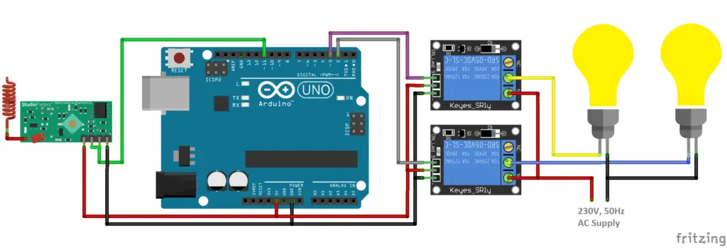
figure 4 – Control multiple light bulbs
#include <RH_ASK.h>
#include <SPI.h>

RH_ASK driver;
const int output_A = 2, output_B = 3;
char receive[32];

void setup()
{
  driver.init();
  pinMode(output_A, OUTPUT);
  pinMode(output_B, OUTPUT);
}

void loop()
{
  uint8_t buf[RH_ASK_MAX_MESSAGE_LEN];
  uint8_t buflen = sizeof(buf);

  if (driver.recv(buf, &buflen))
  {
    memset(receive, 0, sizeof(receive));
    for (int i = 0; i < buflen; i++) {
      receive[i] = buf[i];
    }
    if (strcmp(receive, "Switch_A_ON") == 0) {
      digitalWrite(output_A, HIGH);
    }
    else if (strcmp(receive, "Switch_A_OFF") == 0) {
      digitalWrite(output_A, LOW);
    }
    else if (strcmp(receive, "Switch_B_ON") == 0) {
      digitalWrite(output_B, HIGH);
    }
    else if (strcmp(receive, "Switch_B_OFF") == 0) {
      digitalWrite(output_B, LOW);
    }
  }
}
Multiple device control with Latching switch
Similar to single device latching same string is send for repeated action on same output, the receiver is toggling the state of output. Here ON and OFF operation of two outputs can be controlled by 2 switches.
Refer figure 1 for circuit.
Transmitter
#include <RH_ASK.h>
#include <SPI.h>

const int switch_A = 2, switch_B = 3;
int state = 0, msg_state = 0;
char *msg, *msglast;
RH_ASK driver;

void setup()
{
  driver.init();
  pinMode(switch_A, INPUT);
  pinMode(switch_B, INPUT);
  Serial.begin(9600);
}

void loop()
{
  if (digitalRead(switch_A) == HIGH && state == 0) {
    msg = "Switch_A";
    state = 1;
    msg_state = 1;
  }
  else if (digitalRead(switch_B) == HIGH && state == 0) {
    msg = "Switch_B";
    state = 1;
    msg_state = 1;
  }
  else if (digitalRead(switch_A) == LOW && digitalRead(switch_B) == LOW) {
    state = 0;
  }
  if (msg_state == 1) {
    Serial.println(msg);
    driver.send((uint8_t *)msg, strlen(msg));
    driver.waitPacketSent();
    delay(200);
    msg_state = 0;
  }
}
Receiver
Refer figure – 4 for circuit.
#include <RH_ASK.h>
#include <SPI.h>

RH_ASK driver;
const int output_A = 2, output_B = 3;
int output_A_state = 0, output_B_state = 0;
char receive[32];

void setup()
{
  driver.init();
  pinMode(output_A, OUTPUT);
  pinMode(output_B, OUTPUT);
}

void loop()
{
  uint8_t buf[RH_ASK_MAX_MESSAGE_LEN];
  uint8_t buflen = sizeof(buf);

  if (driver.recv(buf, &buflen))
  {
    memset(receive, 0, sizeof(receive));
    for (int i = 0; i < buflen; i++) {
      receive[i] = buf[i];
    }
    if (strcmp(receive, "Switch_A") == 0) {
      output_A_state = !output_A_state;
      digitalWrite(output_A, output_A_state);
    } else if (strcmp(receive, "Switch_B") == 0) {
      output_B_state = !output_B_state;
      digitalWrite(output_B, output_B_state);
    }
  }
}
Super! Thank you very much!