Ceiling Fan and Light wiring circuit diagram
A single fan and light control using an individual switch is a very commonly used wiring circuit in house, offices, etc.
In the circuit, the phase line is connected parallel to the one pole of the two SPST switches and the neutral line is connected parallel to the neutral terminal of both fan and light. The terminal of switch S2 is connected directly to the phase terminal of the bulb.
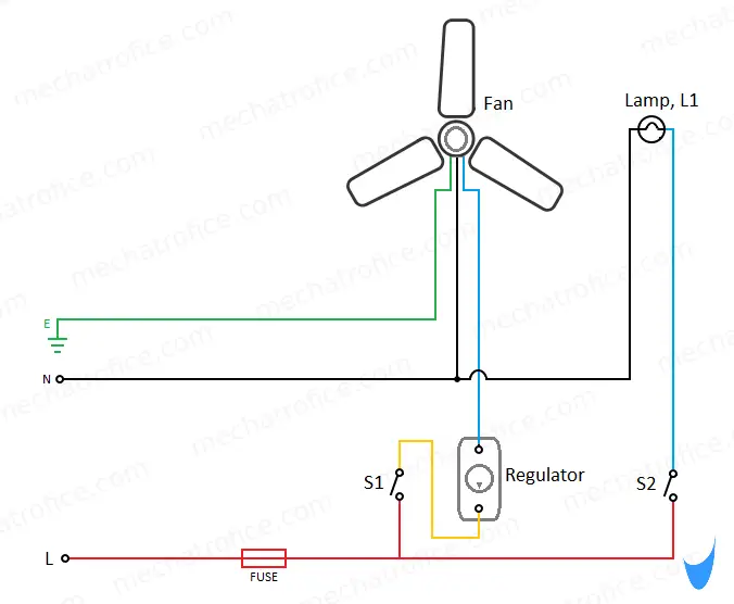
From the terminal of switch S1, a regulator is connected in series with the fan for speed regulation.
Earthing to the fan shown in the circuit is optional, most of the wirings for ceiling fans are two-wire without an earth connection. Because a chance of human contact with the metallic body of a ceiling fan is very rare. If there is a leakage it will be through the ceiling and in modern wirings with sensitive RCCB’s it will trip instantly in event of such earth leakages. An earthing just offer extra safety that eliminates all the possible chance of earth leakage through the ceiling and other metallic or conductive materials.
Materials Required
| Component | specification | Quantity |
| MCB/Fuse | 230V, 50Hz | 1 |
| Lamp | 230V, 50Hz | 1 |
| Fan | 230V, 50Hz | 1 |
| Switch | SPST, 230V, 5A | 2 |
| Regulator | 230V, 50Hz | 1 |
my name is theodidas muzo am from tanzania anytime i follow your page because this page is help me to understand electrical in deep
I won learn more about house wirering