Power Factor Improvement using Capacitor Bank
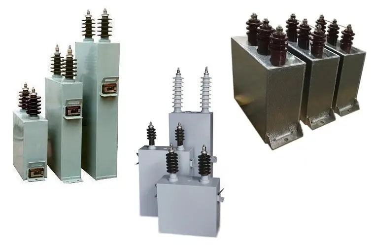 Capacitor Bank is an assembly of capacitors that has the same rating arranged in series or parallel.
In AC power supplies Capacitor Banks are mainly used to improve the power factor of the AC Loads.
Power factor, Pf =cos Φ. The Power factor decreases with an increase in lag or lead of current from the voltage. That is higher the phase angle or phase shift lesser the pf.
cos Φ is maximum at Φ = 0. The value of cos Φ decreases towards +90 and -90.
The current leads to a capacitive load and lags when the load is inductive.
The majority of the industrial loads are inductive in nature because of the use of heavy motors. Due to this cause a lagging current which results in a low power factor. How much the power factor is low that much reactive power in the load.
So apart from active load in kW, reactive power in kvar is consumed by the load which draws more current from the supply. It causes high power consumption compared to the same active load with a high power factor. This waste of supply is a burden for the electricity supply companies as they have to manage the excess power requirement. Thus they demand an improved power factor on the loads. It is the responsibility of the consumer to ensure that the average power factor is not falling below the recommended PF value else electricity supply companies impose fines or penalties on them.
How the power factor can be improved by using a capacitor bank?
As a capacitor can constitute a leading phase shift the capacitor bank compensates for the lagging phase shift of the inductive reactance; the leading current counteracts the lagging current. Thereby it maintains a unity power flow by reducing the overall phase shift and the reactive component when connected in parallel with the load.
Thus an improved power factor offers less current requirement.
In addition to power factor improvement, the capacitor banks improve voltage stability also.
In DC power supplies it acts as a filter that reduces the AC ripple. It can provide a constant DC supply and eliminate sudden spikes and fluctuations in the line.
how to calculate the power factor if a capacitor bank is installed to improve the power factor of an industrial unit from 0.75 to 0.95, the apparent power was 800kVA, calculate the new apparent power
Calculate the initial real power (kW) using the initial power factor:
Initial Real Power (kW) = Initial Apparent Power (kVA) × Initial Power Factor
Calculate the reactive power (kVAR) at the initial power factor:
Initial Reactive Power (kVAR) = Initial Apparent Power (kVA) × √(1 – Initial Power Factor^2)
Calculate the desired reactive power (kVAR) at the new power factor:
Desired Reactive Power (kVAR) = Initial Real Power (kW) × tan(acos(New Power Factor))
Calculate the new apparent power (kVA) using the desired reactive power and the new power factor:
New Apparent Power (kVA) = √(Initial Real Power (kW)^2 + Desired Reactive Power (kVAR)^2)
This new apparent power reflects the improved power factor after the installation of the capacitor bank.
Keep in mind that this calculation assumes a linear load, which might not be the case for all industrial units. It’s also important to verify the type and capacity of the capacitor bank needed to achieve the desired power factor improvement.
*Please check carefully, formulas may have some errors.