Master Switch wiring diagram
In electrical wiring, a master switch is a switch that can ON or OFF or both ON/OFF a group of loads irrespective of their individual ON/OFF switch control.
Using a master ON circuit a group of lamps or loads can be turned ON and kept in ON position even its individual control switches are turned OFF.
Similarly, a master OFF circuit can turn OFF the group of lamps and prevent the lamps from turning ON even its individual switches are turned ON.
A master ON and OFF circuit can either turn ON or turn OFF the lamps irrespective of their individual control.
Master ON switch wiring
Master ON switch is the most common type of master switch wiring used in house wirings.
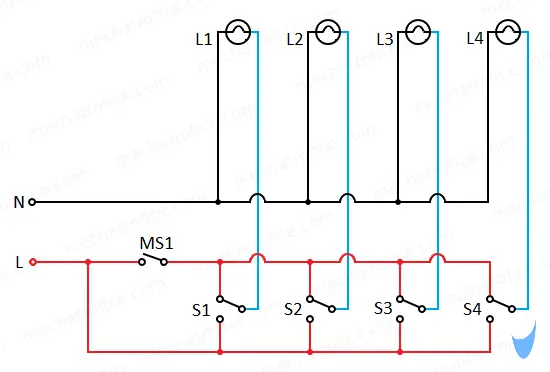
In the circuit, the Master switch (MS1) is an SPST switch and S1, S2, S3, S4 are SPDT switches. The common pole of each SPDT switches S1 to S4 are connected to the respective lamps L1 to L4, also the neutral line is distributed parallel to each lamp.
1st terminal of each SPDT switch S1 to S4 is connected to the Phase line (L) and the other to the phase line through the Master switch (MS1). So, one terminal of the SPDT switch will always have a phase line and the other terminals will have a phase line only if the master switch is turned ON.
Consider the master switch is OFF (MS1 – OFF), in this condition only one terminal of the SPDT switches has the phase line, and all the terminals connected to the master switch remain open. So only switches positioned to the live terminal (connected to direct phase line) will ON the lamp, where switches positioned to open terminal OFF the lamp. So, the switch S1, S2, S3, and S4 can individually control lamps L1, L2, L3, and L4 respectively.
Consider the Master switch is ON, at this condition both the terminals of the SPDT switches have phase line. Hence, in either ON or OFF position of the SPDT switch the common pole has contact to the phase line and the lamp remains ON.
A master ON circuit arrangement can turn ON lamps irrespective of individual position, but this circuit cannot prevent a lamp from turning ON and keep a circuit OFF. For that functionality, a master OFF switch circuit is used.
Master OFF switch wiring
In most of the wiring, the Master OFF feature can be achieved by just turning OFF the MCB of the respective loads. If the Phase line from the MCB is not arranged for a specific group of loads or a switch position for easy access is required, then simply add a switch to the phase line that can isolate the supply to the loads. Then whatever the switch position is no phase line will reach the individual switches.
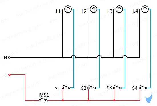
SPDT switches are not required if only needs master OFF function, an SPST switch is enough for that. Because only one throw is required in this circuit.
Master ON and Master OFF switching
Here circuit has the combined functionality of master ON switch and Master OFF switch wiring. This wiring arrangement can turn ON or OFF lamps irrespective of their individual switch positions.
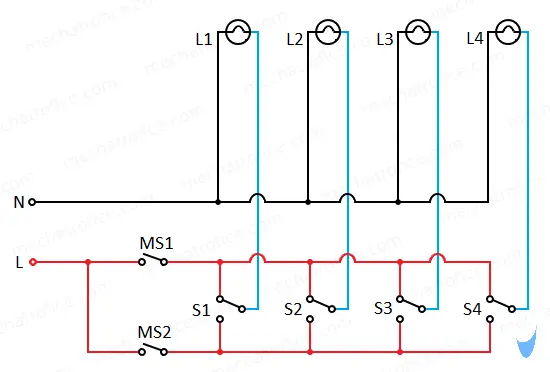
This circuit is the same as the master ON circuit the only change is an additional Master switch (MS2) which is added to the phase line that was previously connected directly to the terminals of switches S1 to S4.
Now we can control both the phase lines connected to the two terminals of the SPDT switches using master switches MS1 and MS2.
Now turning OFF the MS1 and MS2 will completely isolate the SPDT switches from all phase lines, and this state act as master off state.
In normal time, MS1 left open and MS2 needs to turned ON to operate the switches individually. Because in this condition only one throw makes contact to phase line other makes an open contact to the common pole. The switches work in individual control even if the MS2 is turned OFF and kept MS1 ON, but the switch positions to ON/OFF will be just reversed.
If both MS1 and MS2 turned ON then the circuit function as Master ON.
| MS1 | MS2 | Lamps state |
| OFF | OFF | Master OFF – All lamps are OFF |
| OFF | ON | Individual Control ON/OFF Position |
| ON | OFF | Individual Control OFF/ON position (Interchanged) |
| ON | ON | Master ON – All lamps are ON |
It is very good, thanks.
Drow the cercuit Diagram that can control the foolowing lumps
L1 L2 L3 L4
S1 S2 S3 S4
Great job
This is great