Voltage Level Indicator circuit using IC LM339
A voltage level indicator is a circuit that can be used to indicate the voltage range of input supply. Usually, the circuit consists of a sequence of threshold points with the corresponding sequence of LEDs arranged to light ON when the input voltage reaches equal to or above each threshold values.
For example, the reference points of a voltage level circuit are 3V, 6V, 9V, 12V, and the corresponding LEDs are LED1, LED2, LED3, LED4 respectively. If we apply an input voltage of 8V then the LED 1 and 2 becomes ON and the LED 3 and 4 remain OFF. Because the input value is above the reference point 3V & 6V but below 9V & 12V.
The voltage level indicator circuit given here uses a comparator circuit to compare the input values to check whether the input is above or below the reference value.
A comparator is a device that compares two inputs and produces an output that indicates which input is larger.
The two inputs of the comparator are inverting ( – ) and non-inverting ( + ) inputs. The output of the comparator will be in a high state or positive saturation when the input voltage at the non-inverting terminal is larger than the voltage at the inverting terminal. And the output switches to a low state or negative saturation when the input voltage at the inverting terminal is larger than the non-inverting terminal. It simply checks the voltage between two inputs and gives an output either high or low irrespective of the magnitude of difference between them.
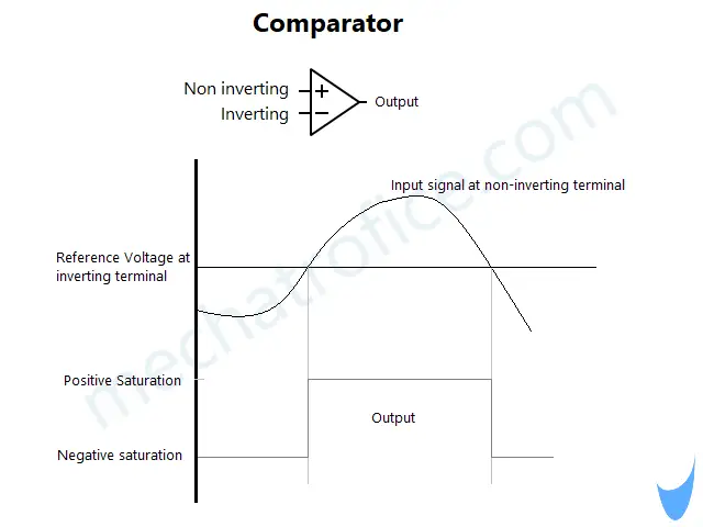
For example, if the input voltage at non-inverting ( + ) = 6V, input voltage at inverting ( – ) = 5.8V. Then the output becomes high as the voltage at the non-inverting terminal has a larger value. If we exchange the above voltage values between two inputs then the inverting terminal will have the larger value and then the output will switch to a LOW state.
Lm339 Comparator IC
The main component of this voltage level indicator circuit is an LM339 IC which is a quad comparator IC that has 4 comparators. So, we can use up to 4 reference values to compare; to check whether the input voltage is above or below the 4 reference points.
Lm339 Pin diagram
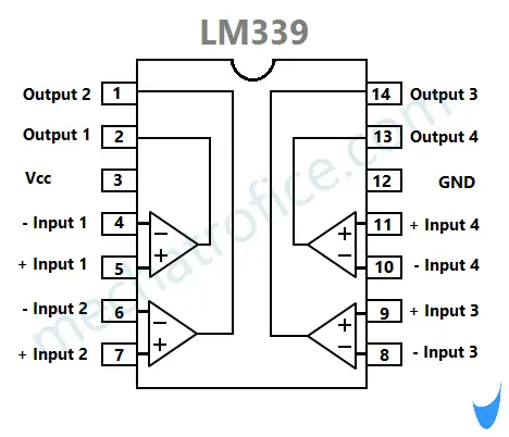
| Comparator | Pin | Function |
| Comparator 1 | 4 | – Inverting input 1 |
| 5 | +Non-Inverting input 1 | |
| 2 | Output 1 | |
| Comparator 2 | 6 | – Inverting input 2 |
| 7 | +Non-Inverting input 2 | |
| 1 | Output 2 | |
| Comparator 3 | 8 | – Inverting input 3 |
| 9 | +Non-Inverting input 3 | |
| 14 | Output 3 | |
| Comparator 4 | 10 | – Inverting input 4 |
| 11 | +Non-Inverting input 4 | |
| 13 | Output 4 |
Working of circuit
Here the reference voltages are obtained by using a voltage divider network of equal resistors (1kΩ). The voltage divider is connected across the supply and each point is connected to the non-inverting terminal of the comparators. In the circuit we have four 1kΩ resistors, the voltage across each resistor will be equal to Vcc/4. If the voltage across the total resistor is 12V then the voltage across each resistor is 12/4 =3V. Hence, the voltage across resistors R1, R2, R3, R4 with respect to GND will be the voltage at the inverting terminal of comparators 1,2,3,4 that is 3V,6V,9V,12V respectively.

The input is connected commonly to the inverting terminal of the four comparators. If the input signal has a value above each reference point then the output of the corresponding comparator act as a sink and the LED lights ON.
Here we have connected the reference values to the non-inverting terminal of the comparator and the input signal to the inverting terminal. So as to switch the output to a low state and act as a sink when the voltage at the inverting input is higher than the non-inverting input.
Why it is not arranged to get a high state at the output when the input voltage is larger than the reference value? Because the output of the LM399 IC has an open collector output hence it doesn’t source the load, it can only act as a sink. The output only provides a path to the ground pin not to the voltage source. Hence, we have to connect the load across the +ve terminal of the supply and the output pin of the comparator, not between output and GND. So, here in the circuit, the anode of the LEDs is connected to the Vcc and the cathode to the output.
In this circuit, we can measure an input voltage of 0 to 12V. Because the reference values are obtained as 3V,6V,9V,12V by dividing it as Vcc/4, Vcc/2, 3Vcc/4, Vcc respectively; Vcc in the circuit is 12V and the difference between each point is Vcc/4.
By scaling the input or reference voltages the same circuit can be used to check a wide range of voltage levels.
If the input voltage is of a smaller range then you can adjust the reference voltage levels by adding a series resistance with resistors R1 to R4. The voltage across the total resistors R1 to R4 will be VT = Vcc – VR5; Voltage across resistors = supply voltage – voltage drop across R5. Then the voltage across the voltage divider is divided into four reference points, VT/4.
To measure higher voltages, use a voltage divider at the input to obtain an input voltage of a particular ratio.
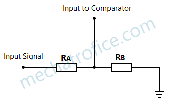
Then the voltage across the RB is the scaled input voltage value given to the comparator respective to the input voltage.
VRB = V(RB/RA+RB) | V – input signal voltage
For example, if the input voltage is of range 0 to 60V, then you can obtain a scale of 0 to 12V by using a voltage divider with resistors, RA=12K, RB = 3K,
Then, VRB = 60(3000/15000) = 12V
So using a voltage divider for a voltage range of 0 to 60V, input to comparators of voltage 3V,6V,9V,12V are generated for input voltages 15V,30V,45V,60V respectively.
Components Required
IC – Lm339
Resistors
R1,R2,R3,R4,R6,R7,R8,R9 – 1KΩ
R5 -10KΩ
LED
D1,D2,D3,D4 – 5mm
Hi, I have just put this circuit together and all I am getting at the moment is the four LEDs gradually dim as I reduce the voltage from 12v to 2v. Also please advise do I need another 12v supply to use in this circuit to compare against. My understanding of the circuit was that I only needed the 12V battery that I was trying to measure its voltage. Therefore the “12V’ is the reference voltage and the “input” is where the battery to be tested is attached?
Thanks for any help you can provide.
Yes, you need a 12V supply to power the circuit, which is also used as the reference voltage.