Arduino Ohmmeter : How to Measure Resistance Using Arduino
An ohmmeter is an instrument that measures the electrical resistance across two points of a body or material. The device usually works by applying a small quantity of current to the test resistance which is connected in series with a reference resistance of known value. The unknown resistance is then calculated from the voltage and known resistance values by applying in the equations of voltage divider circuits.

Serial Monitor based PC Ohmmeter
In a series circuit the voltage drops across resistors are in direct proportion to their magnitude of resistance. According to Ohm’s law V = IR; V- voltage drop across resistor, I – current through the resistor, R – resistance value. The current through all resistors in a series circuit is same then voltage drops across each varies proportinaly with resistance,
V1 = IR1, V2 = IR2; I is same for both resistors. Hence V1 α R1, V2 α R2, that is higher the resistance higher the voltage drop across it.
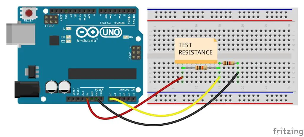
In the circuit, the test resistance is connected across the 5V pin and Analogread pin A0. A known reference resistance (Rrefer =1000) is connected to the analog input and GND. The analog input reads the voltage across (V1) the reference resistance.
Then test resistance value can be obtained by the equation,
Rtest = (5 - v1) * Rrefer / v1;
For measuring always try to maintain the value of the reference resistor near to the test resistance. How much the value of test resistance can be made closer to the reference resistance, that much accuracy can be obtained in the readings. That is the error will be larger as the value of the unknown resistor is considerably larger or smaller than the value of the known resistor.
Code
float v1, Rtest, Rrefer = 1000;

void setup() {
  Serial.begin(9600);
}
void loop() {
  v1 = analogRead(A0);
  v1 = v1 * (5.0 / 1023.0);
  Rtest = (5 - v1) * Rrefer / v1;
  Serial.print("Resistance = ");
  Serial.print(Rtest);
  Serial.println("ohm");
  delay(1000);
}
Change the reference resistor value in the code with the value of resisitor used in circuit. The value of reference resistance in the circuit and the code should be always the same. The value of the reference resistance can be adjusted in the program by replacing the value of Rrefer. For serial monitor ohmmeter, the code has an input option to enter the reference resistance value. So we can enter the test resistance value during each start or reset.
float v1, Rtest, Rrefer = 0;

void setup() {
  Serial.begin(9600);
  Serial.print("Enter refernce resistance = ");
  while (Rrefer == 0) {
    Rrefer = Serial.parseInt();
  }
  Serial.print(Rrefer);
  Serial.println("ohm");
}
void loop() {
  v1 = analogRead(A0);
  v1 = v1 * (5.0 / 1023.0);
  Rtest = (5 - v1) * Rrefer / v1;
  Serial.print("Resistance = ");
  Serial.print(Rtest);
  Serial.println("ohm");
  delay(1000);
}
The reference resistance should have an accurate value. If the tolerance of the reference resistance is not negligible, it should be considered while setting the actual Rrefer value. The tolerance in the value of reference resistance will considerably affect the reading. So the chance of error increases with the variation of the refer resistance from its rated value.
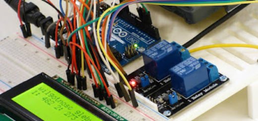
LCD Digital Ohmmeter
The only change in the LCD resistance meter is just an addition of LCD interface instead of the serial monitor display.

Code
#include <LiquidCrystal.h>
float v1, Rtest, Rrefer = 1000;
LiquidCrystal lcd(12, 11, 5, 4, 3, 2);

void setup() {
  lcd.begin(16, 2);
  lcd.print("Rtest = ");
}

void loop() {
  v1 = analogRead(A0);
  v1 = v1 * (5.0 / 1023.0);
  Rtest = (5 - v1) * Rrefer / v1;
  lcd.setCursor(8, 0);
  lcd.print(Rtest);
  lcd.print("ohm");
  delay(1000);
}
This is a neat concept, but unfortunately I don’t think it’s very accurate. When I saw this project, I had the thought that I might use it to read thermistor values to build a little device I could easily carry around to help me diagnose problems at work. I built the circuit on a breadboard and used a 16 character LCD screen to show the readings. Using an 8.2 Kohm resistor as my reference, I plugged in a thermistor that at room temperature has values around 10 Kohm, and 5-8 Kohm at the temperatures I usually test. I quickly took a reading with my DMM before plugging it in and got about 11.5. With the arduino plugged into my bench supply only I was getting readings around 7 Kohm. With it also plugged into the USB port of my computer, they were closer to 9. Plugged only into USB it was reading around 13. It seems that the readings this circuit provides are highly dependent on the source of power available, and it is therefore fairly useless unless a person were to do extensive testing and take special care to adapt it to a single, consistent power supply. It seems you could never for instance run this on batteries, because your values would change dramatically as the available power dropped.