LCD Arduino Tutorial – How to connect LCD with Arduino
16×2 LCD display
LCD displays are a common part of most of the embedded system projects, as it is the simplest readout method to display user instruction, text or output values, etc.
This article explains the basics of AJHD162A LCD 16×2 display and its interface with the Arduino UNO R3.
A JHD162A LCD 16×2 display is a 16 pin interface module consists of 16 columns x 2 rows with
CHAR. DOTS:5 x 8 (5 columns x 8 rows)
The pins and functions of the JHD162A LCD 16×2 module display are described as below.
| Pin NO | Name | Function |
| 1 | VSS | Ground |
| 2 | VCC | +5V DC |
| 3 | VEE | Contrast adjust |
| 4 | RS | Register select |
| 5 | R/W | Read or write |
| 6 | E | Enable |
| 7 | DB0 | Data bit |
| 8 | DB1 | Data bit |
| 9 | DB2 | Data bit |
| 10 | DB3 | Data bit |
| 11 | DB4 | Data bit |
| 12 | DB5 | Data bit |
| 13 | DB6 | Data bit |
| 14 | DB7 | Data bit |
| 15 | LED+ | Backlight LED+ |
| 16 | LED – | Backlight LED- |
JHD162A pin description
Pin1 (Vss): Connected to the Ground terminal of the supply
Pin2 (Vcc): An input supply of DC voltage +5V is connected to this pin.
Pin3 (V0): Contrast adjust: The contrast adjust pin is connected to the wiper terminal of the potentiometer, the end terminals are connected to +5V and ground. The contrast of the LCD display can be adjusted by varying the voltage at the VEE pin. A grounded VEE pin also works fine.
Pin4 (Register Select): The LCD JHD162A module has two registers such as data register and command register.
Either the data register or command register will be selected at a time. An active high state of the RS pin selects the Data register and a low state selects the command register.
when the Data Register has selected the input at the data pins will be considered as data and will be displayed on the screen of the LCD matrix. And if the command register selected, the data will be selected as instructions to control the matrix module.
Pin5 (R/W): This pin is used to select read and write modes.
A logic HIGH state of R/W pin selects read mode, i.e. read from the register and logic LOW at R/W pin selects write mode, i.e. write to the register.
Pin6 (E): It is to enable the LCD module. A HIGH to a LOW signal at the enabling pin enables writing to the registers 8 data pins (D0 -D7).
Pin7 (DB0) – Pin14 (DB7): DB0 to DB7 are 8 data bit pins. The commands and data are sent through these pins. The states of these data pins (high or low) are the bits that you’re writing to a register when you write, or the values you’re reading when you read. State low at these pins represents a bit ‘0’ and high as bit ‘1’.
Pin15 (LED+) & Pin16 (LED-): The anode and cathode of the LED backlight. Connect Pin15 LED+ to a 5V supply and Pin16 LED- to ground.
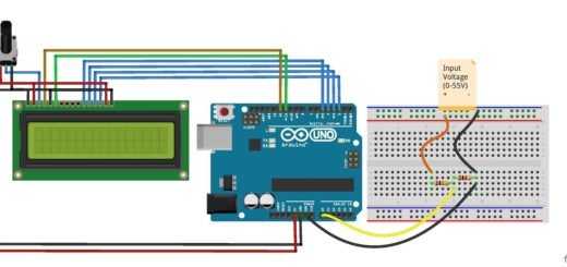
Arduino LCD Connection
For the Arduino interface, the LCD pins are connected as follows to the Arduino UNO R3 board.
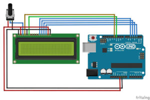 LCD Enable (pin6) pin to digital pin 11, LCD RS (pin4) pin to digital pin 12
The LCD module is interfaced with the Arduino in the 4-bit mode. Thus only the Data pins DB4 to DB7 of the LCD are connected and the remaining data bit pins DB0 to DB3 are left disconnected.
The connection of LCD data pins DB4 to DB7 with the corresponding pins of Arduino is listed below.
LCD (pin11) D4 pin to digital pin 5
LCD (pin12) D5 pin to digital pin 4
LCD (pin13) D6 pin to digital pin 3
LCD (pin14) D7 pin to digital pin 2
Vss (Pin1) Connected to the Ground.
Vcc (Pin2) An input supply of DC voltage +5V is connected to this pin.
VEE (pin3) connected to terminal 2 of the potentiometer, terminal 1 is connected to +5V and terminal 3 to the ground.
LCD R/W (pin5) pin is connected to the ground to select write mode.
LED+(pin15) is connected to a +5V supply and LED- (pin16) is connected to the ground.
Arduino LCD display Sample code
#include <LiquidCrystal.h>
LiquidCrystal lcd(12, 11, 5, 4, 3, 2);
int i=0;
void setup() {
  lcd.begin(16, 2);
}

void loop() {
  lcd.setCursor(4,0);
  lcd.print("Mechatrofice");
  for(i=0;i<4;i++){
    lcd.scrollDisplayLeft();
    delay(500);
  }
   for(i=0;i<4;i++){
  lcd.scrollDisplayRight();
   delay(500);
}}
Try the above sample code which moves the text “Mechatrofice” to and fro on the 16×2 LCD display.
LCD to Arduino interface using I2C/IIC Adapter
Another easy method to interface an LCD display with Arduino is by using an I2C serial interface adapter module.
The advantage of the LCD I2C interface is it keeps the circuit neat and simple and it is less complex in connection. For bigger circuits, this is the most feasible method because a smaller number of Arduino pins will be reserved for the LCD display.
In the above method, the LCD is connected directly to Arduino through a parallel connection. By using an I2C interface, parallel communication is converted to serial I2C communication. I2C is a serial protocol with a two-wire interface method using communication lines SDA (Serial DATA Line) and SCL (Serial Clock Line). So including two wires for VCC & GND, the connection to LCD from the Arduino can be limited to a 4-wire circuit.
In the parallel LCD interface, the library used was LiquidCrystal.h. But for an I2C interface, LiquidCrystal_I2C.h and wire.h libraries are required; wire.h library is for I2C communication and the LCD library allows the Arduino board to control Liquid Crystal displays.
The Wire.h library is already inbuilt in Arduino IDE that allows us to communicate with I2C/ TWI (Inter-Integrated Circuit /Two Wire Interface) devices. To add the LiquidCrystal I2C library either download.zip file or add directly from the library manager.
Download Library
https://github.com/fdebrabander/Arduino-LiquidCrystal-I2C-library, or
https://github.com/johnrickman/LiquidCrystal_I2C – In this library, wire.h is already included in the LiquidCrystal_I2C Library, it doesn’t need wire.h to imported additional in the sketch. The below code has an inbuilt wire library with the LCD library so the #include <wire.h> is commented in the code(//#include <wire.h> ), just include wire.h if the LCD library requires it.
In Arduino IDE, Sketch > Include Library > Add .ZIP Library > Select and open the downloaded zip file. The Arduino sketch given on this page is suitable to work with the above two libraries.
Install from the library manager
Sketch > Include Library > Manage libraries > search for LiquidCrystal_I2C and install the library.
Connect the LCD and I2C adapter as in the circuit or directly plug the 16 male header pins of the I2C module to the LCD female header pins, then the serial pins of the I2C adapter can be connected to the Arduino. The contrast of the LCD can be adjusted by the potentiometer on the I2C module.
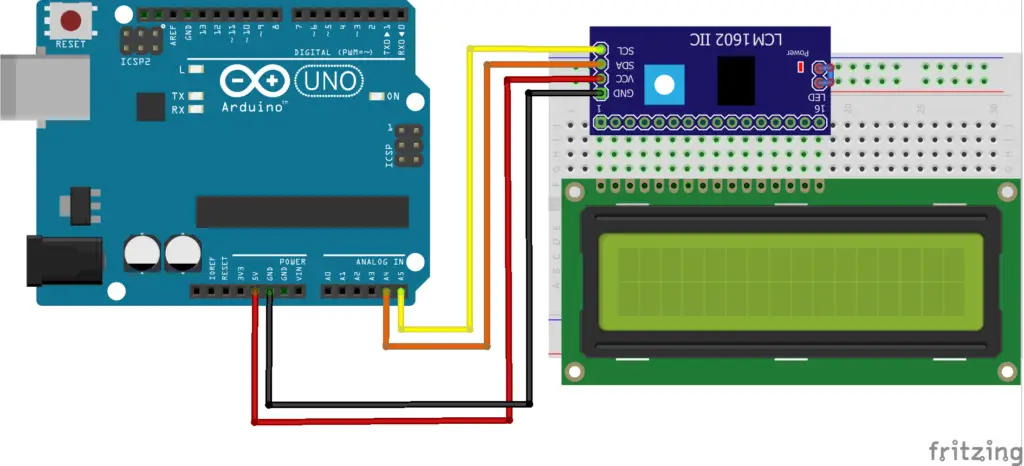
I2C to Arduino connection
| I2C Adapter pin | Arduino Uno pin |
| GND | GND |
| VCC | 5V |
| SDA | A4 (Analog pin 4) |
| SCL | A5 (Analog pin 5) |
Arduino LCD code using I2C
#include <LiquidCrystal_I2C.h>
//#include <wire.h>
//I2C address 0x27
LiquidCrystal_I2C lcd(0x27,16,2); //16x2 display
void setup()
{
  lcd.init();// initialize the lcd
  lcd.backlight();// Backlight ON
  lcd.setCursor(1,0);// 2nd column,1st row
  lcd.print("Hello, world!");
  lcd.setCursor(0,1);// 1st column,2nd row
  lcd.print("Arduino I2C/IIC");
  delay(3000);
}

void loop()
{
  lcd.clear();
  delay(500);
  lcd.setCursor(0,0);
  lcd.print("_");
  delay(500);
}