Automatic Light Control Circuits
These circuits can be used for different automatic light sensing projects including automatic night lamp, automatic street light controller, dark sensor circuits, etc.
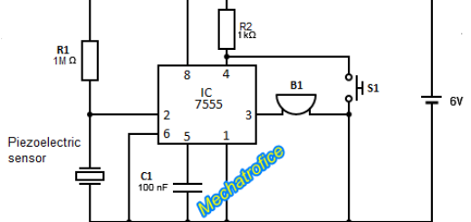
Automatic night lamp circuit using IC 555 and LDR
An automatic night light circuit controls the switching of light by sensing the surrounding light intensity. The circuit ON the LED light, when the incident light intensity falls below a particular limit. And OFF the light when the incident light is above the limit.
In the circuit, the threshold and trigger pin of the NE555 has connected with a voltage divider network. It can obtain a trigger voltage which is half of the voltage at threshold pin. In a 555 IC, when the threshold pin has a voltage above 2/3Vcc, the output switches to a low state. And output switches to a high state when the voltage at trigger pin falls below 1/3Vcc.
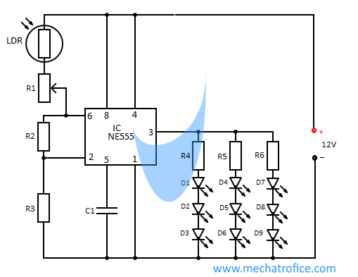
The LDR (Light dependent resistor) has a negative coefficient of resistance with the light intensity. So, when the intensity of the incident light is high, the voltage drop across the LDR decreases. Thus, the voltage across the threshold pin reaches the threshold value and the Light OFF. Similarly, with the decrease in light intensity, the voltage across the threshold pin and the trigger pin decreases and the Light ON.
The light sensitivity of the circuit can be adjusted by the varying the potentiometer R1.
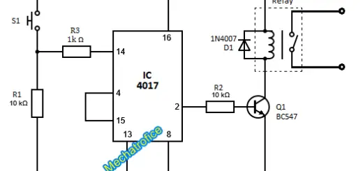
To operate an external lamp with the same circuit, interface a relay with the output pin3 of the 555 IC. So it can control 230V AC lights or similar externally powered lights with the same circuit. For relay interface, refer the circuit diagram of the automatic power cut off circuit. The relay can be connected similarly as shown in that circuit.
Components required
IC – NE555
Resistor – R1 – pot 407k, R2,R3 – 82K, R4, R5, R6- 220Ω
LDR
Capacitor – C1 – 0.01uf
Diode – D1 – D9 – White LED
Automatic Light Switch using LDR and Transistor
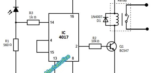
This circuit adjusts the output light with respect to the ambient light intensity. That is when the incident light from the surroundings reduces, it automatically increases the brightness of the LED. Similarly, inverse as the light increases. Hence this circuit can consider as a simple light level regulator. Because it show’s a gradual variation in light, not a steady ON-OFF switching.
In the circuit, the sensing part of the circuit is a photoresistor or LDR, (Light Dependent Resistor) which have a negative coefficient of resistance with respect to the intensity of light. That is the value of resistance varies inversely proportional to the light intensity.
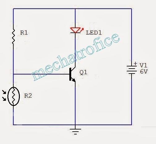 In the above circuit, the LDR is connected across the Base and Emitter terminal of the transistor. So, in accordance with the variation in the intensity of light the base current inversely changes. Thereby adjusts the collector current or current through the LED.
Components required
Transistor – Q1- BC547
Resistor – R1 – 39k, R2 – LDR -5mm
LED -White
Supply – 6v battery
Automatic ON-OFF Light using Op-amp
Here unlike from a transistor circuit, the output has only steady ON state or OFF state for varying ambient light intensity. The LED ON and OFF when the amount of incident light rise or fall with respect to a threshold intensity value. Whereas the transistor circuits lights LED gradually.
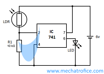 In the circuit the op-amp act as a comparator. In a comparator circuit, the output will be at either positive saturation or at negative saturation. The comparator output will be high (positive saturation) when the input voltage of the non-inverting terminal is greater than the inverting terminal. And low output (negative saturation) state for a higher inverting voltage. When both terminals kept open, the output will be positive saturation voltage (due to offset voltage of practical op-amp ICs).
As the light falls on the LDR, its resistance decreases and a voltage drop created across the resistor R1. In the circuit the non-inverting terminal is open. And thus for a small rise in the inverting terminal voltage, the output switch to negative saturation and the LED will reverse biased. In full darkness, the resistance of LDR will be high and the voltage drop across is maximized. Whenever the full voltage drops across the LDR, the op-amp switches to positive saturation and ON the LED. The circuit has a high sensitivity to light, a small variation in LDR resistance can switch the circuit OFF.
The sensitivity of the circuit can be varied by adjusting the resistance R1. Because variation in the value of R1 can alter the threshold point to a small extent. For a wide adjustment, a reference voltage value is required to be added to the non-inverting terminal. A potentiometer or voltage divider circuit can be used to obtain a variable reference voltage.
Components required
Op-amp IC – LM741
Resistor – R1 – 39k
LDR -5mm
LED -white 6V
Supply – 6v battery
For here circuits, the LDR should properly be placed to sense the incoming light.
Automatic LED Emergency Light Circuit
The automatic power failure emergency light charges the battery when the power is ON and automatically lights ON the LED when the power goes out.
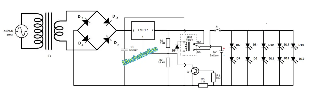
The circuit consists of a battery charging section, with a regulated and limited current DC supply of 6V and relay controlled LED lights.
The relay energized when the supply has a live line. So the common pole of the relay contacts to the normally open terminal. Thus, the battery connects to the input DC supply and charges.
When power fails, the relay changes to Normally closed position and the battery switches to the LED light. Here we are using a five parallel set of two 3V LEDs in series. So, without any resistors, a 6V battery can connect directly to LEDs.
The switch S1 can be used to select whether the light to be always ON automatically or to ON/OFF manually. For a permanent automatic operation, the switch can be closed always or shorted instead.
Emergency light – Components required
LM317 – Voltage Regulator
Resistor – R1, R4 – 1k, R2 – 3.9k, R3- 2ohms
Capacitor – C1 – 2200uf
Diode – D1-D5 -1N4007, D6-D15 – White LED 3V
Transistor – Q1- BC547
Transformer – T1- 230V/6V,1A
Relay – SPDT relay 6V
Switch – S1 – SPST
I have 2 lights controlled by Occupancy sensor switches on circuit #1 the 2 OS’s also control 1 exhaust fan on circuit #2, there is also a 3 pos switch that turns all on off and auto, I am having trouble wiring this, is there a diagram that displays this operation?
Hi
Kindly share me LDR control main stand by lamps circuit with DPDT relay for lamp failure alarm