Arduino LED voltage level indicator
Commonly the voltage values are displayed in decimals using LCD displays, serial data, etc. Here shows a simple project to indicate only the voltage levels, that can be used for battery percentage monitors, battery chargers, etc. The voltage level indicator shows the level of input voltage with respect to the four reference states of voltage values. The given circuit is designed to operate in a voltage range of 0V up to a maximum of 10V. The four reference level is divided into 0V,2.5V,5V and 7.5V. The LEDs indicates when the input voltage reaches a value greater than or equal to these reference values.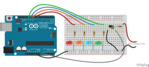
Here, the voltage level indicator shows the level of input voltage with respect to the four reference states of voltage values. The given circuit is designed to operate in a voltage range of 0V up to a maximum of 10V. The four reference level is divided as 0V,2.5V,5V and 7.5V. The LEDs indicates when the input voltage reaches a value greater than or equal to these reference values.
Green – ON when the input voltage value is greater than or equal to 7.5V.
Blue – ON when the input voltage value is greater than or equal to 5V
Orange – ON when the input voltage value is greater than or equal to 2.5V
Red – ON when the input voltage value is greater than or equal to 0V
First we are measuring the input voltage using Arduino. The maximum input voltage limit of the Arduino is 5V. So for a maximum input voltage of 10V, we are using a voltage divider combination to adjust the input voltage. Two 1k resistors are used for voltage division, which drops input voltage equally across it. That is the voltage at analog input pin will be half of the actual input voltage. In the Arduino code, the analog input reading of range 0 to 1023 is mapped between 0 to 10, because the voltage divider obtains half of the actual input.

Also, a Zener diode has connected between the analog input and the GND terminal, to protect the Arduino pin from high input voltages. We are using a 4.7V Zener diode to protect the Arduino pin from input voltages above the maximum limit. As the zener diode is about 4.7V the maximum measurable input voltage of the circuit will be 9.4V. If the applied voltage is above 9.4V, excess voltage will drop across the first resistor and the Zener diode maintains a constant voltage across the analog input.
Voltage monitor arduino Code
float volt, voltage;

void setup() {
pinMode(9, OUTPUT);
pinMode(10, OUTPUT);
pinMode(11, OUTPUT);
pinMode(12, OUTPUT);
}

void loop() {
  volt = analogRead(A0);
  voltage = map(volt, 0, 1023, 0, 10);
  if (voltage >= 0) {
    digitalWrite(9, HIGH);
  }
  else {
    digitalWrite(9, LOW);
  }
  if (voltage >= 2.5) {
    digitalWrite(10, HIGH);
  }
  else {
    digitalWrite(10, LOW);
  }
  if (voltage >= 5) {
    digitalWrite(11, HIGH);
  }
  else {
    digitalWrite(11, LOW);
  }
  if (voltage >= 7.5) {
    digitalWrite(12, HIGH);
  }
  else {
    digitalWrite(12, LOW);
  }
  delay(1000);
}
Hi, nice project, but you forget to put PinMode in code….
👍