Half-Wave and Full-Wave Rectifier Circuits: A Complete Guide
Direct current flows only in one direction, which means it has a constant polarity across its terminals. Where an Alternating current periodically changes its direction of the current, that is an alternating polarity at the terminals.
A rectifier is a circuit that converts AC to DC and this conversion process is called rectification. In simple words, a rectifier converts the bi-directional flow of current to a unidirectional flow, which maintains a constant polarity across the load. It can be done by either blocking the reverse flow of current or by redirecting the reverse flow to one direction.
Half Wave rectifier theory
A half wave rectifier clips the negative half cycles and allows only the positive half cycles to flow through the load. Thus it utilizes only the one-half cycle of the input signal.
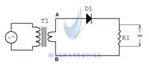
During the positive half cycle (A- Positive & B- Negative) of the signal, the diode will be forward biased and conducts the current through the load resistance. And on negative half cycle (A- Negative & B- Positive), the diode will be reverse biased and prevents the current to flow in the opposite direction. So the polarity of the output terminals keeps unchanged and obtains a unidirectional current through the load.
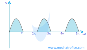
Half Wave Rectifier equations and values
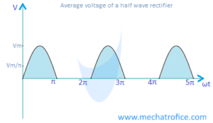
Average voltage, Vaverage = Vm/π | Average Current, Iaverage = Im/π
Rms Voltage, Vrms = Vm/2 | Rms Current, Irms = Im/2
Ripple factor = 1.21
Maximum efficiency = 40.6%
Transformer utilization factor (TUF) = 0.287
Form factor = 1.57
peak factor = 2
Full Wave rectifier theory
It converts the complete cycles of the AC signal to DC. Both positive and negative half cycles of the AC signal is converted to a unidirectional flow of current.
Full wave center tap rectifier circuit
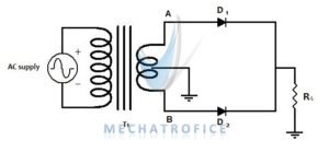
A center tapped full wave rectifier works only with a center tap transformer or with a similar common potential point across the terminals. The center tap act as a common zero potential terminal in both half cycles.
On the positive half cycle (A- Positive & B- Negative), the diode D1 is forward biased and diode D2 is in reverse biased. Hence the current flow through D1 and the load resistance, from terminal A to center tap.
On the negative half cycle (A- Negative & B- Positive), the diode D2 is forward biased and diode D1 is reverse biased. Current flows through D2 and load resistance, from the B terminal to the center tap of the transformer.
The biasing of diodes changes alternately with respect to change in the polarity of terminals.
In the center tap rectifier, the output DC voltage will be half of the total output voltage of the secondary winding. Because the load is always on half of the secondary winding.
Full Wave Bridge Rectifier circuit
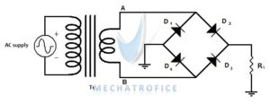
The bridge rectifier consists of 4 diodes in a bridge circuit configuration. From a center tap rectifier, the bridge rectifier has a difference only in the circuit arrangement. The efficiency, ripple factor, average value, RMS value all are same except the transformer utilisation factor(TUF). Because in a center tap rectifier the transformer winding should consider separately.
The bridge rectifier has an advantage over the center tap, that is it works without a center tapped transformer or a common ground.
On the positive half cycle, (A- Positive & B- Negative) diode D2 & D3 are in forward biased. D1 & D4 are in reverse biased, thus the conduction path forms through diode D2, load resistance, and diode D3.
Similarly, on the negative half cycle (A- Negative & B- Positive) diode D4 & D1 is in forward biased. Diode D3 & D2 are in reverse biased. Current flows through D4, load resistance and D1.
The biasing of the diodes alternates in each half cycle and creates a same polarity across the load. Hence, in both half cycles the load resistance has the same direction of the current.
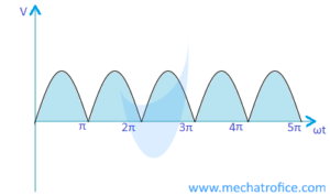
Full wave Rectifier equations and values
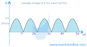
Average voltage, Vaverage = 2Vm/π | Average Current, Iaverage = 2Im/π
RMS Voltage, Vrms = Vm/√2 | RMS Current, Irms = Im/√2
Center tap rectifier, Transformer utilization factor (TUF) = 0.693
Bridge rectifier, Transformer utilization factor (TUF) = 0.812
Ripple factor = 0.482
Maximum efficiency = 81.2%
Form factor = 1.11
peak factor = √2
Average value of rectifier
The arithmetic average of all the instantaneous values of a signal is called as its average value.
Average value = area under curve / base
Average value of sine wave
The average of a sinusoidal wave form can be calculated as,
Average value = Area of a unit cycle/ base length of a unit cycle

Derivation to mathematically find the resultant average value for a unit cycle of a sine wave,
V = Vmsinωt, Vm – Maximum Voltage or peak voltage, V – Instantaneous voltage.
The average value of a function f(x) on an interval [a, b] = (1/b-a) a ∫b f(x) dx.
The area under the curve is the Integral of function f(x) in the interval from a to b. And the base length is the difference between the limits b and a.
For a unit cycle of a sine wave, the area of the region has obtained by integrating the sine wave equation and the base length from the difference of limits 0 and 2π.
Hence the average voltage, Vavg = Vm/2π 0∫2π sinωt dωt | Vm/2π is a constant value.
= Vm/2π ( 0 ∫π sinωt dωt + π ∫2π sinωt dωt ) = Vm/2π [ – cosωt]0π + Vm/2π [ – cosωt]0π .
= Vm/2π [- cosπ + cos0] + Vm/2π [- cos2π + cosπ]
Therefore, Vavg = Vm/2π [1+1] + Vm/2π [-1-1] = 2Vm/2π – 2Vm/2π = 0
The average value of a sinusoidal alternating quantity for a complete cycle will be equal to zero. Because, the positive and negative half cycle is equal in magnitude and thus the total value cancels out on summation.
Average value of Half wave rectifier
Negative half cycles are absent in the output wave form of a half wave rectifier. So, in order to find the average value of the rectifier, the area under the positive half cycle has divided by the total base length.
The area under the positive half cycle is the integral of sinusoidal wave equation from the limits 0 to π. The total base length is the difference of limits of a complete cycle (2π – 0 = 2π), which includes the base length of both the positive and negative cycles.
The average output voltage of a half wave rectifier can be derived as,
Average voltage, VDC = Vm/2π 0∫π sinωt dωt
= Vm/2π [ – cosωt]0π = Vm/2π [- cosπ + cos0]
= Vm/2π [1+1] = 2Vm/2π = Vm/π
The average voltage equation for a half wave rectifier is VDC = Vm/π.
Average value of Full wave rectifier
In a full wave rectifier, the negative polarity of the wave will be converted to positive polarity. So the average value can be found by taking the average of one positive half cycle.
Derivation for average voltage of a full wave rectifier,
The average voltage, VDC = Vm/π 0∫π sinωt dωt
= Vm/π [ – cosωt]0π = Vm/π [- cosπ + cos0]
= Vm/π [1+1] = 2Vm/π
Average voltage equation for a full wave rectifier is VDC = 2Vm/π.
So during calculations, the average voltage can be obtained by substituting the value of maximum voltage in the equation for VDC.
RMS value of rectifier
RMS (Root mean square) value is the square root of the mean value of the squared values.
The RMS value of an alternating current is the equivalent DC value of an alternating or varying electrical quantity. RMS value of an AC current produces the same amount of heat when an equal value of DC current flows through the same resistance.
RMS value of a signal = √ Area under the curve squared / base length.
For a function f(x) the RMS value for an interval [a, b] = √ (1/b-a) a ∫b f2(x) dx.
RMS value of sine wave
RMS Value = √ Area of half cycle squared / half cycle base length

The RMS value of a sine wave can be calculated by just taking the half cycle region only. Because the area of positive half cycle squared and negative half cycle squared have the same values. So the derivation will be same as it for a full wave rectifier.
The RMS Voltage of a sine wave, VRMS = Vm/ √2, Vm – Maximum voltage or peak voltage.
RMS value of Half wave rectifier

In a half wave rectifier, the negative half cycle will be removed from the output. So, the total base length(2π) should be taken from the interval 0 to 2π.
The RMS voltage, VRMS = √ Vm2/2π 0∫π sin2ωt dωt
= √ Vm2/2π 0 ∫π(1 – cos2ωt) / 2 ) dωt = √ Vm2/4π [ωt – sin2ωt / 2]0π
= √ Vm2/4π [ π – (sinπ) / 2 – (0 – (sin0) / 2)] = √ Vm2/4π ( π ) = √ Vm2/ 4
Therefore the RMS voltage, VRMS = Vm/ 2
RMS value of Full wave rectifier
 The RMS voltage, VRMS = √ Vm2/π 0∫π sin2ωt dωt
= √ Vm2/π 0 ∫π(1 – cos2ωt) / 2 ) dωt = √ Vm2/2π [ωt – sin2ωt / 2]0π
= √ Vm2/2π [ π – (sinπ) / 2 – (0 – (sin0) / 2)] = √ Vm2/2π ( π ) = √ Vm2/ 2
RMS voltage, VRMS = Vm/ √2
Peak factor of rectifier
The peak factor is defined as the ratio of the maximum value to the RMS value of an alternating quantity.
Peak factor = Peak value / RMS value
RMS voltage of a half wave rectifier, VRMS = Vm/2. Where Vm is the Maximum or peak voltage.
Then the Peak factor of half wave rectifier can be calculated as,
Vm / VRMS = Vm / ( Vm / 2 ) = 2 Vm / Vm = 2
Similarly, For a full wave rectifier, the RMS voltage VRMS = Vm / √2
Therefore, the Peak factor value of full wave rectifier = Vm / Vm/ √2
= Vm √2 / Vm = √2 = 1.414
Form factor of rectifier
The ratio of RMS value to the average value of an alternating quantity is known as its form factor.
Form factor = RMS value / Average value
RMS voltage of a half wave rectifier, VRMS = Vm / 2 and Average Voltage VAVG= Vm/π, Vm is the peak voltage.
Form factor of half wave rectifier = VRMS / VAVG = ( Vm /2 ) / ( Vm / π )
= π Vm / 2 Vm = 1.57
For a full wave rectifier, the RMS voltage VRMS = Vm / √2 and the average Voltage,
VAVG = 2 Vm / π
Form factor value of full wave rectifier = ( Vm / √ 2 ) / ( 2Vm / π )
= π Vm / 2√2 Vm = 1.11
Ripple factor of rectifier
The ratio of the RMS value (root mean square) of the AC component to the DC component of the output is defined as the Ripple factor and is denoted by γ.
Ripple factor, γ = VAC/VDC | VDC is the average value of the DC output.
VRMS = √ VDC2 + VAC2 or IRMS = √ IDC2 + IAC2
VAC = √ VRMS2 – VDC2
Therefore the ripple factor equation is, γ = √ (VRMS2 – VDC2) / VDC2 = √ ( VRMS / VDC)2 – 1
To calculate the ripple factor of a half wave and full wave rectifier, just substitute the RMS and Average value of the respective rectifier in the above equation.
Ripple factor of Half wave rectifier
RMS Voltage of a half wave rectifier, VRMS = Vm / 2 | Vm is the peak voltage.
Average Voltage of a half wave rectifier, VAVG = Vm / π
Ripple factor, γ = √ ( [ (Vm/ 2) / (Vm / π) ]2 -1 ) = √ ( π / 2 )2 – 1 = 1.21
Ripple factor of Full wave rectifier
RMS Voltage of a full wave rectifier, VRMS = Vm / √2
Average Voltage of a full wave rectifier, VAVG = 2 Vm / π
r = √ ( [ (Vm/√ 2 ) / (2 Vm / π) ]2 – 1 ) = √ ( π / (2 √ 2) )2 – 1 = 0.48
Efficiency of rectifier
The ratio of DC output power to the AC input power of a rectifier is called as its efficiency. It is denoted by η.
Rectifier efficiency, η = DC output power/input AC power = PDC / PAC
Efficiency of Half wave rectifier
IRMS = Im / 2 , PAC = IRMS2 (rf + RL) = ( Im / 2)2 (rf + RL)
Vm is the peak Current |
PDC = IAVG2 RL = ( Im / π)2 RL
For a half wave rectifier, the Efficiency η = PDC / PAC = ( ( Im / π)2 RL ) / ( ( Im / 2)2 (rf + RL) )
= 4 RL / π2 (rf + RL) = 0.405 RL / (rf + RL)
Therfore the maximum efficiecy = 40.5%
Efficiency of Full wave rectifier
Similarly for a full wave rectifier,
IRMS = Im / √ 2 , PAC = ( Im / √ 2)2 (rf + RL)
PDC = ( 2 Im / π)2 RL
For a half wave rectifier, the Efficiency η = PDC / PAC = ( ( 2 Im / π)2 RL ) / ( ( Im / √ 2)2 (rf + RL) )
= 8 RL / π2 (rf + RL) = 0.810 RL / (rf + RL)
Maximum efficiecy = 81.0%
Hence we can see that, the efficiency of a full wave rectifier is double than that of a half wave rectifier.
AC to DC
- Rectifier circuit
- Filter circuit
- Voltage regulator circuit
Very fine notes
Helped me a lot
Searched the entire google and got most satisfactory result. Thank you very much.
Well done great noteservice able to understand very clearly thank u so much
thank you so much
😈😈😈😈😈😈
this is well explained thank u
Well explained
Thanks guys
In some books Vdc=0.45Vrms is given because they take Vm=√2 Vrms for halfwave rectifier like solid state elections by BL theraja
Vrms of a half-wave rectifier, Vrms = Vm/2.
Hence Vm = 2Vrms.
Vdc = Vm/π = 2Vrms/π = 0.636Vrms.
For a full wave rectifier, Vm=√2 Vrms
Vdc = 2Vm/π = 2√2Vrms/π = 0.9vrms
What is the value of v-out in a full and half wave rectification circuit?
Full-wave rectifier
Vm- maximum value or peak voltage of the output.
Average output, Vdc = 2Vm/π
RMS output, Vrms = Vm/√2
Half wave rectifier
Average output, Vdc = Vm/π
RMS output, Vrms = Vm/2
I have never seen note like this before.
All my needs were met.
I love this.
efficiency of full wave rectifier is 81.2%
Yes, it can be 81.2%; the final equation for % of efficiency becomes derived as (8/π2)*100.
If we substitute π with value 3.14 then it gives 81.139 ≈ 81.2%.
While calculating with π value of 3.14159 (while taking π directly from scientific calculators, etc) it gives 81.0570%; given in the above article.
quite informative
Hi. May I know the book references? Thanks
I have a concern. In my laboratory where we supply our circuit with the same input VRMS, I found that we are getting half the voltage of the full bridge rectifier for our full wave center-tapped rectifier. Does this have something to do with connection to the center of the secondary winding for our transformer?
In the center tap rectifiers, the output voltage will be half of the total output voltage of the secondary winding. To get the same voltage as the bridge rectifier gives, the voltage between the line and center tap needs to have a voltage equal to Vrms.
What is the relationship between DC current to load, measured after the full-wave bridge, and AC current to the load measured without a full-wave bridge in place, i.e., as measured by a wattmeter? Example: Solenoid coil, 148.67 ohms, 3945 turns of AWG 32 wire, at 120/60 Hz measures as follows on wattmeter: 120.54 VAC, 0.090 A, 6.75 watts. Now put a full-wave bridge between AC source and the solenoid and you measure this: 120 VAC/60 Hz, 105.7 VDC, 0.635 A DC. Question here is, “Power is now approximately 67 watts DC , but without the bridge is 6.75 watts AC? Can you explain?
Excellent write-up.
I believe you do not take into account the diode forward voltage junction drop. Should we subtract 2 x 0.6V for a full wave / bridge rectifier and only 1 x 0.6V for a full wave rectifier?