Controlling a LED using arduino serial monitor
Arduino Serial Communication
A Serial communication is a method of transmitting data as a train of 1s and 0s, i.e. only one bit for a clock cycle of binary coded data. Or one bit at a time, sequentially on a communication channel. It is a contrast to parallel communication, whereas in parallel system multiple bits are sent through several parallel paths. In a parallel system number of bits transmitted per clock is equal to the number of parallel paths. That is, a 4-bit channel can transmit any of the 16 binary states for a single clock cycle.
 In a serial communication to transfer a byte, the data is transferred as a sequence of 8 bits as one by one. Each bit is either high state 1s or low state 0s.
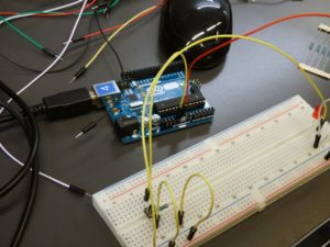
In Arduino boards, the serial connection can be made either via serial port (type B USB) or by digital pins 0 (RX) and 1 (TX). An Arduino IDE includes a serial monitor, a built-in terminal to communicate with an Arduino board.
You can open the serial monitor by,
Press ctrl+shift+M
Tools/Serial Monitor
Or click the magnifier icon in the top right corner of the Arduino IDE.
Serial controlled LED
Both the programs use the built-in LED, which is driven by digital pin 13. Change the pin number as according to your connection (if you are connecting an LED to the Arduino ).
 In this project the LED can be on and off by a keyboard input, that is simply a character or decimal input.
In the first sketch, we are using a character to ON and OFF the LED. ‘H’ or ‘h’ represents the active high state and the ‘L’ or ‘l’ represents the active low state.
Arduino code 1
void setup() {
  pinMode(13, OUTPUT);
  Serial.begin(9600);
}
void loop() {
  if (Serial.available() > 0) {
    char state = Serial.read();
    if (state == 'H' || state == 'h') {
      digitalWrite(13, HIGH);
      Serial.println("LED ON");
    }
    if (state == 'L' || state == 'l') {
      digitalWrite(13, LOW);
      Serial.println("LED OFF");
    }
  }
  delay(50);
}
In this sketch, we use decimal values 1 and 0 for control. Using Decimal 1 for ON and decimal 0 for OFF; considering binary representation for state levels HIGH and LOW.
Arduino code 2
void setup() {
  pinMode(13, OUTPUT);
  Serial.begin(9600);
}
void loop() {
  if (Serial.available() > 0) {
    char state = Serial.read();
    if (state == '1') {
      digitalWrite(13, HIGH);
      Serial.println("LED ON");
    }
    if (state == '0') {
      digitalWrite(13, LOW);
      Serial.println("LED OFF");
    }
  }
  delay(50);
}

Hi, this is nice and simple, thanks a lot! I wouldn’t how brightness of the LED could be controlled with serial input?
Any clues?
Try this code
// Serial LED brightness control. int led = 9; int brightness = 0; // Enter values from 0 to 255. void setup() { Serial.begin(9600); pinMode(led, OUTPUT); Serial.print("Brightness = "); } void loop() { while (Serial.available() > 0) { brightness = Serial.parseInt(); Serial.println(brightness); Serial.print("Brightness = "); } analogWrite(led, brightness); delay(50); }That worked great! Thank you so much. Seems really simple too 🙂
I have a C++ program that reads Xbox control pad input and runs the values of stick and trigger position. I’m trying to output those values through the serial port to my Arduino… We shall see!
Thanks again!
thanks
not working for me 🙁 not sure why
Are you getting any error?