LED chaser circuit using IC 4017 and 555
An LED chaser or LED running light can be used as a decorative light, fancy light, chasing taillight for vehicles, etc.
The circuit consists of a 555 astable multivibrator circuit and a 4017 counter using IC. The output of the 555 generates a square wave or clock input for the decade counter. For each positive edge triggering of the clock input, the counter shifts the high state of the output in a sequence from output 0 to output 9.
In a 4017 counter IC, only one output will be high at a time and the remaining outputs will be in the low state. And the shifting cycle repeats like a ring counter. Thus the LEDs will visually seem like a rotating.
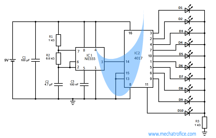
Here the Chaser circuit is designed with an ON time of 0.047s for each LED. The speed of the chaser can be varied by adjusting the time period of the clock input. That is the time period of the 555 astable multivibrator circuit, which can be calculated as T = .69 (R1+2R2) C.
Components required
IC – IC1 – NE555, IC2 – 4017
Resistor – R1,R3 – 1K,R2 – 6.8k
Capacitor-C1 – 100uf,C2 – 4.7uf,C3 – 100nf
LED – D1-D10 – 5mm
Supply – 9V
LED knight rider circuit
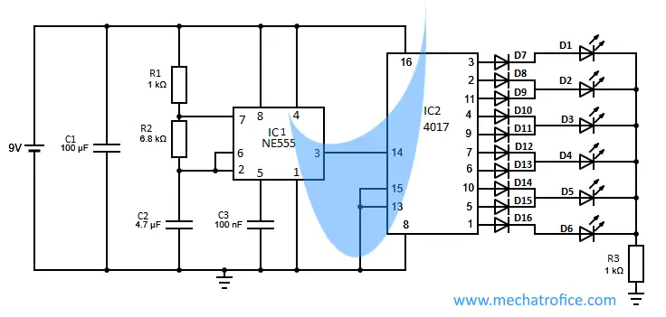
This circuit configuration is almost the same as the above circuit, the only difference is in the knight rider circuit the sequencing of the LED is arranged with diodes to obtain a to and fro motion of light. The output from 0 to 5 is connected as same as in the above chaser circuit, but from output 6 onwards it is connected in reverse sequence. Thus the LED lights one by one and moves forward, once the 6th LED is reached the direction reverses and move towards output 0. This movement repeats like a swing action.
components required
IC -IC1 – NE555, IC2 – 4017
Resistor – R1,R3 – 1K, R2 – 6.8k
Capacitor – C1 – 100uf, C2 – 4.7uf, C3 – 100nf
LED – D1-D6 – 5mm LED, D7-D16 – 1N4007
Supply – 9V

Question on LED chaser circuit. Getting a small project together for a scout group. Most of the 4017 & 555 circuits are pretty much the same with the variance of the resistor and capacitor values from ground to Vcc across pins 2,6,&7. Most of the circuits I’ve seen leave pin 5 open, but a few have shown a capacitor to ground.
Two questions.
1. The first circuit I bread boarded from another site did not have the capacitor, and after less than a minute it stopped chasing, but would continue for another short time with a power cycle. Any hints on what I did wrong?
2. What does putting the capacitor to the pin 5 control get you?
Be warned, I have some electronics knowledge from school MANY years ago, but just enough to be dangerous.
1. Can you share the circuit? It seems weird. I couldn’t find any reason for such a result. Normally the 4017 and 555 chaser circuits consist of a 555 astable multivibrator which provides square wave clock input to 4017 IC.
2. The threshold and triggering voltages can be overridden by adjusting the voltage at Pin 5. That is the applied voltage at pin 5 is the threshold voltage and its half is triggering voltage. So if we don’t need to change the threshold voltage or trigger voltage values it can be left open. Then the threshold voltage will be 2/3Vcc and the trigger will be 1/3Vcc. While pin 5 is left open it has chances to affect by small fluctuations and noises so in order to avoid that a bypass capacitor is using at pin5.
For reference: http://mechatrofice.com/circuits/555/555-timer-multivibrator-circuits
I want delay to be around 0.5 s what should be resistor and capacitor value
T = 0.69 (R1+2R2) C2 // using the formula
0.7246 = (1k +2R2) 4.7uf
Replace R2 approximately equal to 76,589ohms.
Or try calculating with the available components you have; http://mechatrofice.com/calculator/555-multivibrator.