Capacitor, Inductor, LC, Pi Filter circuits for DC power supply
A DC filter circuit is a device that eliminates ripples in an input signal and allows DC to pass to the output. DC filters circuits are mainly used with the rectifier outputs to obtain a stable, smooth DC voltage from a pulsating DC input.
Referring to the output waveform of a full wave rectifier we can find that the output DC is consists of two positive half cycles. Both the half cycles begin and end in 0V, that is during each cycle the voltage is pulsating between Vminimum = 0V and Vmaximum. Using a filter, the output fluctuation can be minimized to an extent where the difference between Vmaximum and Vminimum is considerably low.
By reducing the ripple voltage (Vripple) filter circuit improves the average value of the DC. When the Vminimum value near to Vmaximum it delivers an output voltage level that can be clipped by a voltage regulator at below the minimum voltage so as to obtain a stable dc voltage. That is the voltage above the minimum value is bypassed or removed using a Zener diode and a constant supply voltage is attained.
The following passive filters are by using a capacitor, inductor, and using the combination of both components.
- Capacitor filter
- Choke or Inductor filter
- LC filter
- Pi filter or π filter.
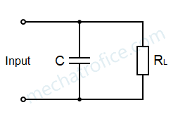
Capacitor Filter
A shunt capacitor filter is the simple and most common filter circuit used in both half wave and full wave rectifiers; it is just a capacitor connected parallel to the load.
 Full wave input
 Full wave input
From the waveform, it is clear how the capacitor maintains the voltage across the load during the decrease in voltage of each half cycle. A simple capacitor can eliminate a considerable amount of voltage fluctuation and increase the average DC voltage.
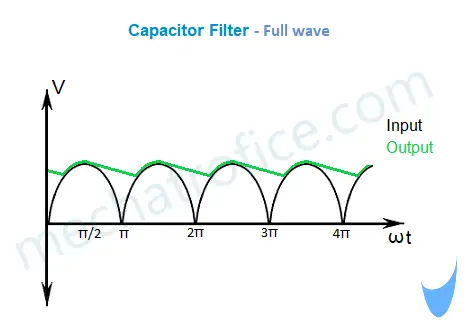
On the first half of the halfwave, the voltage rises from 0 to Vm as a function of V = Vm sin(wt); wt ranges from 0 to π/2. The capacitor charges during this period up to the maximum voltage value Vm. In the next quadrant, the rectifier output voltage decreases from Vm to 0 as a sinewave function for π/2 to π. During this period the capacitor discharges and the voltage across the load become equal to the voltage across the capacitor; that is the voltage across the load is a function of the voltage across a discharging capacitor. As shown in the above waveform, the voltage across the load will be reduced only to the minimum voltage value where the capacitor discharges till the charging starts again in the next half cycle.
Half wave input
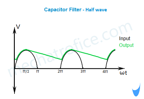
For half wave rectifier output, a shunt capacitor filter is the most suitable method to filter. Here the capacitor has to discharge from Vmaximum of the first half-wave at π/2 to the point after 2π where the input voltage becomes equal to the capacitor voltage. Compared to a full form rectifier the ripple factor for a half-wave rectifier output is high. Because the capacitor is discharging for a long period due to the absence of a complete half cycle and the voltage is dropping to a lower voltage.
- The capacitor opposes sudden voltage changes across it. But for sudden fluctuations or ripples, it offers an easy path.
- It maintains a constant voltage across the load.
- The capacitor discharge rate increases with the load current. Hence the voltage across the capacitor is more constant if the load current is less.
- It can work with both Half wave and full wave rectifier.
- The main advantage of the filter is small in size, low cost, simple circuit.
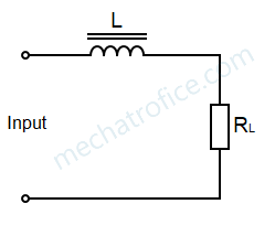
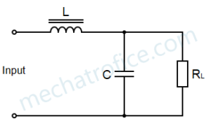
Choke filter or inductor filter
In L-filter an Inductor or choke is connected in series with the load. The inductor always opposes any change in current and it has a tendency to maintain a constant current through it. By connecting an inductor series with the load, it blocks fluctuations and maintains a smooth current flow.
An inductor store energy in the form of a magnetic field. When the input decreases it releases the stored magnetic energy to maintain the same amount of current flowing through the inductor.
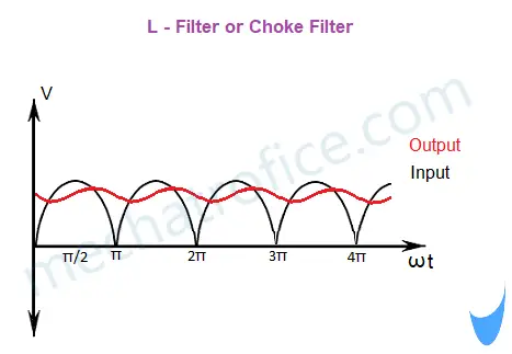
The action of an inductor depends upon the current through it and it requires current to flow at all times. Therefore, filter circuits consisting of inductors can only be used together with full wave rectifiers.
A single choke or L filters are not commonly used as a filter, it is always used with a capacitor to form a filter circuit called as LC filter.
- The property of an inductor is to oppose any change in the current but easily pass a steady DC.
- It maintains the current flow constant.
- The filtering improves with an increase in current. Hence, if the load current is high much smoother the waveform.
- The disadvantage of the choke filter is it is not suitable for half-wave rectifiers.
- The output voltage is less compared to the capacitor filter.
LC filter
An LC filter is a combination of a capacitor and a choke filter with properties of both filters.
The choke blocks the AC component and Pass DC. The capacitor bypasses further fluctuations and provides DC across it.
As briefed above, the fluctuation across the capacitor is reduced if the load current is less. whereas an inductor fluctuates less if the load current is high. These two different natures of capacitor and inductor make an LC filter to work effectively independent of load current.
- Low ripples
- Like choke filter LC filters are also not suitable for half wave rectifiers.
Pi filter or π filter
A pi filter is a shunt capacitor filter followed by an LC filter which is arranged like the Greek letter π, hence it is called a pi filter. The pi filter gives steadier and smoother DC compared to other filters.
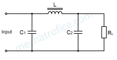
The shunt capacitor C1 does the main filtering. The voltage across the C1 can be expected as a similar waveform of the capacitor filter. Unlike connecting directly to an LC filter here most of the ripples are removed, hence it can further improve the output by the filtering of the LC section.
- High output voltage with less ripple
- The main disadvantage of a pi filter is its larger size and cost compared to other filters.
- A pi filter is suitable to use with both half wave and full wave rectifier because the C1 provides a continuous voltage to the inductor.
AC to DC
- Rectifier circuit
- Filter circuit
- Voltage regulator circuit
it has been decades since i did linear power supply design (and i wasn’t very good at it), and i don’t remember how to choose the inductor value. BTW, i always used to make C2 bigger than C1 in a pi filter, so as to limit inrush current (somewhat). do U think that was wrong?
Yes, Inrush crush decreases with the decrease in the value of C1.