How to send receive SMS from GSM modem using arduino
Interfacing sim800 / sim900A GSM module with arduino
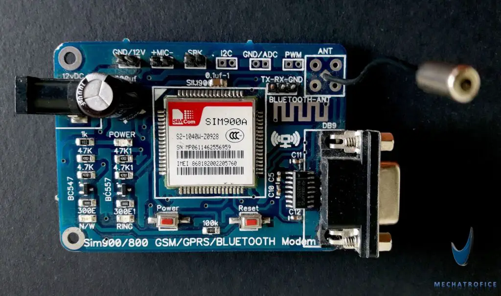
Here describes the interfacing between a SIM 800 GSM / SIM 900A GSM module with an Arduino board via TTL serial communication.
Arduino gsm module pinout
| Arduino pin | GSM modem pin |
| RX | TX |
| TX | RX |
| GND | GND |
For a TTL serial connection, connect the pins from the GSM device to Arduino as, Rx pin to TX pin and TX pin to Rx pin. Or if the software serial is used, connect to the declared Transmitter and Receiver pins. If the Arduino code uses the serial communication as Serial.begin(9600), the TX and RX pins will be default TX and RX pins of the AVR microcontroller which is labelled on the Arduino UNO board. So just plug to TX pin (pin 1) and the RX pin (pin 0).
E.g: – SoftwareSerial mySerial (2, 3); // RX digital pin 2, TX digital pin 3.

GSM modems may also have a female RS232 serial port for direct connection to PC. In order to work directly with hyper terminal or similar serial terminals using AT commands.
GSM modem booting
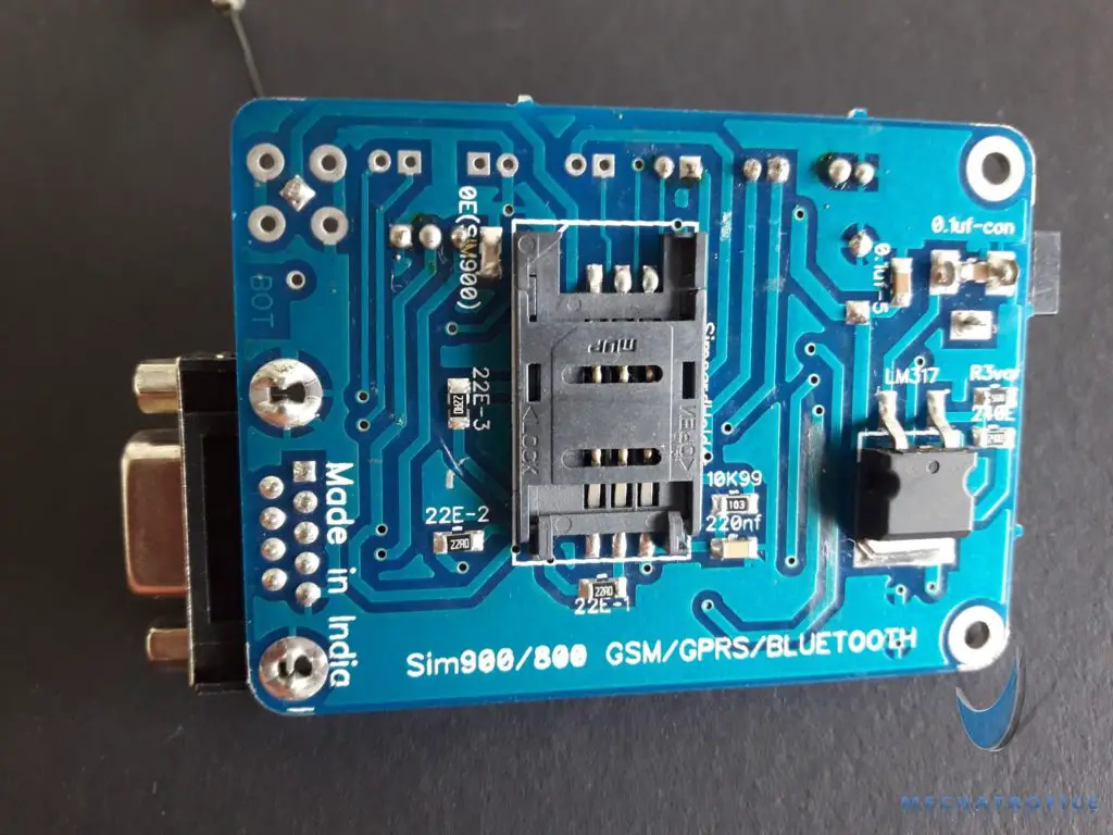
Insert the SIM card into the SIM socket of the module and lock it.
The GSM module requires a considerable amount of power to establish a network connection, and for operations. So power from the Arduino board will not be enough for it. So an external power is required for most GSM modules.
The GSM module Commonly has a 12V DC input, which can be connected either via DC socket or through connector pins. Plug a 12V adapter into the Socket or power it by connector pins on the board.
On powered up, the power LED gets ON and the Network Status LED starts to blink. The network LED blink every second and after when the Modem registers the network, the LED will blink in every 3 seconds. The GSM module takes some time, around 60 seconds to establish a connection with mobile networks.
Send sms using gsm module with Arduino
Here we are sending TEXT messages from GSM modem with Arduino UNO using AT commands.
Connect GSM device to Arduino as Rx and TX pin of the GSM module to TX and Rx pin of the arduino respectively; as explained above in interfacing. Using the below code the GSM module can be directly connected to the Arduino serial pins.
Arduino GSM SMS code
void setup()
{
  //Set Exact Baud rate of the GSM/GPRS Module.
  Serial.begin(9600);
  Serial.print("\r");
  delay(1000);
  Serial.print("AT+CMGF=1\r");
  delay(1000);
  /*Replace XXXXXXXXXX to 10 digit mobile number &  ZZ to 2 digit country code*/
  Serial.print("AT+CMGS=\"+ZZXXXXXXXXXX\"\r");
  delay(1000);
  //The text of the message to be sent.
  Serial.print("HELLO WORLD");
  delay(1000);
  Serial.write(0x1A);
  delay(1000);
}
void loop()
{
}
The set of operation code is placed in the void setup (). Each time when the Arduino is powered ON’s an SMS will send, as the void setup function only run once. Or Resetting the Arduino board (press the reset switch on the Arduino board) also sends a message.
In the AT commands,
AT+CMGF=1\r, put the modem in SMS text format mode.
AT+CMGS=\”+ZZ XXXXXXXXXX\”\r, The SMS will send to the 10 digit number written as XXXXXXXXXX with 2 digit country code ZZ.
Here the TEXT is “Hello world”, replace it with the TEXT need to be sent.
0x1A, it is the hexadecimal of the decimal character code 26, which is Substituted (SUB) symbol in ASCII control characters.
Send SMS using push switch
In this device whenever the switch is pressed, a text message (text in the code) will send to the number specified in the code. When the pushbutton is pressed, the Arduino sends the AT commands to the GSM module, for a text SMS; the GSM module works with the “AT commands”.
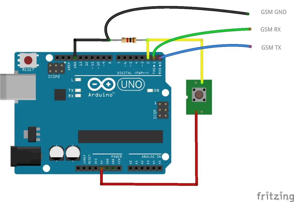
Connect the TX, RX and GND pins from the Arduino to the GSM as labelled in the diagram. Then connect the push switch between the 5V and pin2. Add a pull-down resistor across the pin2 and Ground. The Pin2 is configured as the input pin. When the pin2 reads an active high state, the sketch inside the if condition will be executed. And the SMS sends.
A variable called state is also added to the condition function of the program, it is to prevent multiple sending of SMS on a single switch press. The “if” condition becomes true only when the digitalRead at pin 2 is high and the value of variable state is ‘ 0 ‘. The value of variable state is initialized as ‘ 0 ‘. On pressing the switch, the “if” condition becomes true, that the SMS sends and the state value set to ‘ 1 ‘. Only when the switch is released the state value sets back to ‘ 0 ‘. Only the switch press after the setback of the state to ‘ 0 ‘ makes the if condition true. So a long press will not send multiple SMS, only press after a release sends the next SMS. That is, each consecutive press sends each SMS.
Arduino GSM send SMS code
int state = 0;
const int pin = 2;
void setup()
{
  //Set Exact Baud rate of the GSM/GPRS Module.
  Serial.begin(9600);
}
void loop()
{
  if (digitalRead(pin) == HIGH && state == 0) {
    Serial.print("\r");
    delay(1000);
    Serial.print("AT+CMGF=1\r");
    delay(1000);
    /*Replace XXXXXXXXXX to 10 digit mobile number & ZZ to 2 digit country code*/
    Serial.print("AT+CMGS=\"+ZZXXXXXXXXXX\"\r");
    delay(1000);
    //The text of the message to be sent.
    Serial.print("HELLO WORLD");
    delay(1000);
    Serial.write(0x1A);
    delay(1000);
    state = 1;
  }
 if (digitalRead(pin) == LOW && state == 1) {
    state = 0;
  }
}
Receive SMS using GSM module
Here the GSM module has to interface with the arduino using software serial and the received SMS will be displayed through the serial monitor.
Arduino gsm module pinout software serial
| Arduino pin | GSM modem pin |
| 2 | TX |
| 3 | RX |
| GND | GND |
Read SMS from a message storage area Arduino code
#include <SoftwareSerial.h>
SoftwareSerial serial(2, 3); // RX digital pin 2, TX digital pin 3.

void setup()
{
  Serial.begin(9600);
  serial.begin(9600); //Baud rate of the GSM/GPRS Module
  serial.println("AT+CMGF=1\r");
  serial.println("AT+CMGR=1\r");//Read SMS at location 1.
  delay(1000);
}
void loop()
{
  if (serial.available() > 0) {
    int    c = serial.read();
    Serial.write(c);
  }
  delay(100);
}
Replace the serial.println(“AT+CMGR=1\r”); with
serial.println("AT+CNMI=2,2,0,0,0\r"); - To read newly arrived SMS.
serial.println("AT+CMGL=ALL\r"); - To list all received messages.

Sir how to send current location via sms to phone using gsm module and aurdino
Refer Arduino GPS receiver.
Use the GSM receiver code to get the coordinates, then Send the values of longitude and latitude variables (variable “slat” & “slon” in the GPS receiver code) through SMS.
Sir how can I send location with Google maps link with fingerprint sensor module.
Refer: http://mechatrofice.com/arduino/send-gps-location-via-sms
Replace switch input condition (if condition to check digital pin input) with fingerprint verification check.
This is the complete code to display almost all the available data in the GPS. If you need only the latitude and longitude values use the code given in the article.
#include <SoftwareSerial.h> #include <TinyGPS.h> TinyGPS gps; SoftwareSerial serialgps(4,3); int year; byte month, day, hour, minute, second, hundredths; unsigned long chars; unsigned short sentences, failed_checksum; void setup() { Serial.begin(9600); serialgps.begin(9600); Serial.println(""); Serial.println("GPS Shield QuickStart Example Sketch v12"); Serial.println(" ...waiting for lock... "); Serial.println(""); } void loop() { while(serialgps.available()) { int c = serialgps.read(); if(gps.encode(c)) { float latitude, longitude; gps.f_get_position(&latitude, &longitude); Serial.print("Lat/Long: "); Serial.print(latitude,6); Serial.print(", "); Serial.println(longitude,6); gps.crack_datetime(&year,&month,&day,&hour,&minute,&second,&hundredths); Serial.print("Date: "); Serial.print(month, DEC); Serial.print("/"); Serial.print(day, DEC); Serial.print("/"); Serial.print(year); Serial.print(" Time: "); Serial.print(hour, DEC); Serial.print(":"); Serial.print(minute, DEC); Serial.print(":"); Serial.print(second, DEC); Serial.print("."); Serial.println(hundredths, DEC); Serial.print("Altitude (meters): "); Serial.println(gps.f_altitude()); Serial.print("Course (degrees): "); Serial.println(gps.f_course()); Serial.print("Speed(kmph): "); Serial.println(gps.f_speed_kmph()); Serial.print("Satellites: "); Serial.println(gps.satellites()); Serial.println(); gps.stats(&chars, &sentences, &failed_checksum); } } }Can I send sms to multipal mobile no with single gsm card
Yes, you can. It has nothing with the GSM card, it is completely up to what you have written in Arduino code.
Any code for sending SMS to multiple mobile numbers with a single gsm card sir.
Just repeat the same code to send SMS by adding a new number and message.
Or the number can be placed in an array, number[] = {“AT+CMGS=\”+ZZXXXXXXXXXX\”\r”,—-other numbers—-,”AT+CMGS=\”+ZZXXXXXXXXYY\”\r”}
Then by using number[0],number[1] separate numbers can be selected.
please is there a sample code i can see on sending sms to multiple reciepients?
Did You do this work sir/Madam
Sir how to send data of ultrasonic sensor using Arduino and gsm
Add code for ultrasonic measurement with the GSM code. Refer: Ultrasonic distance measurement.
Pls help with Sample code for proper synchronization
sir the module i have is SIM800L EVB which is the version 2 of SIM800. .my problem is the NET(LED) is blinking every seconds whch means it does not connected to the network. how can i possibly fix this ? thank you for the help. more power !
Maybe its due to lack of signal strength. Make sure the spot has enough signal coverage, or try at different locations, also adjust the antenna. You should try it for a few minutes to register a connection with the service provider.
Many times I had brand new but defective modules, so first make sure it is working.
sir i need a code in which sms is send by sim900 by push button and by receiving the sms by sim900( on or off)sms relay activate or off plz i need help
Hi sir I am using sim900a GSM module how to send SMS to multiple numbers using esp8266 please share if any code
I need a code for make a voice call by sim900 by push button.
The sms keep sending mutiple times even i don’t press the button
Most probably a circuit connection issue. Check pull-down resistors are properly connected.
sir I want the code for sending current location via latitude and longitude to the mobile phone by using gsm 900a module, Neo 6mGps module
and arduino uno
Integrate the code for GPS receiver with the code for GSM.
Refer : GPS receiver using arduino
Under the area for – “//The text of the message to be sent” in the code for GSM. Use,
Serial.print("Latitude :"); Serial.println(slat, 6); Serial.print("Longitude:"); Serial.println(slon, 6);How can I send SMS and current location from GSM900A and GPS SIM28ML using switch
I think this is the right project you need. Refer: Send GPS Location Via SMS with switch press.
I want how to gsm send the message .full details and working of gprs,interfacing of GSM and ARDUINO.
I am making smart dustbin. In it I have used Ultrasonic sensors, I have used aurdino Uno, Ultrasonic sensor and gsm 800.Whenever someone comes against Ultrasonic sensor, you can write a program to get messages from gsm’s help.
Could you please detail?
How to send SMS to multiple no.
You can either add the same code repeating once again with another number. Or you can add number numbers to an array and use “for loop” to call array.
sir, the code for send sms using push button, sends sms even without me pushing the button…how do i fix that
my code:
#include
SoftwareSerial sim808(7,8);
int state = 0;
const int pin = 2;
void setup()
{
sim808.begin(9600);
//Set Exact Baud rate of the GSM/GPRS Module.
Serial.begin(9600);
delay(100);
}
void loop()
{
if (digitalRead(pin) == HIGH && state == 0) {
sim808.print(“\r”);
delay(1000);
sim808.print(“AT+CMGF=1\r”);
delay(1000);
sim808.print(“AT+CMGS=\”+2348176996281\”\r”);
delay(1000);
sim808.print(“Distress Signal, HELP!!!”);
delay(1000);
sim808.write(0x1A);
delay(1000);
state = 1;
}
else {
state = 0;
}
}
im using sim808
Most probably it is due to false input. Check and ensure that the pull-down resistors are properly connected between the Input and GND terminals.
I have a microschema Sim300DZ, do you have a the seal for Sim300DZ?
Sir , i used the same code , but the sms not send to the phone it just printed in the serial monitor . What can i do ??
Actually the code provided for SMS send, uses arduino default serial port which communicates on digital pins 0 (RX) and 1 (TX). Hence you will get the same data in the serial monitor, if opened.
Upload the code and connect the pins of the GSM device to Arduino as, Rx pin (GSM) to TX pin (arduino pin 1) and TX pin (GSM) to Rx pin (arduino pin 0).
Sir can give the code by combining it as sms gps traking
Refer : http://mechatrofice.com/arduino/send-gps-location-via-sms
Sir, it is keep sending sms when input maintain and i dont want like this, just only one sms event input still maintain, pls help
Try the code now, a small change has been made in the “if” condition.
My code just only read the input without “&& state ==1” in condition to send SMS when input in active, let me try to add “&& state==1” in code and update the result. Thks Sirs
You are welcome.
it is well done, thanks so much
sir ,your explanation is perfect.sir i am using ultra sonic sensor with gsm . In my case i have used if statement that if(distance>10) the gsm will sent sms to mobile number but in my case the object always greater than 10 cm.so the gsm sent the sms continuously.I need to sent sms only once for time period of two hours.please help me with code
Did you mean to send the sms always once every 2 hours or once every 2 hours if the distance value is above 10cm and unchanged, but need to send once if it comes below 10cm irrespective of 2 hours interval?
I am doing a project called “IOT Based underground fault locator”. I am using a 16X2 lcd display with the circuit to show the fault distance…Now i want to add a GSM module to see the fault distance in my smart phone. What should be the code?
Refer the here code in the post for send SMS. Use sgsm.print(“Y: “); sgsm.println(dist2); like lcd.write(“Y: “); lcd.print(dist2);.
sir can gsm be operated if i connect it to th 5 v pin on arduino or should i connect it with 12 v dc battery??
GSM modules require considerable amount of power. It is better to drive with an external supply.
i need a code without using push button on gps and gsm module and i have to get msgs of locations to my mobile sir! is that possible send me the code
Refer: http://mechatrofice.com/arduino/send-gps-location-via-sms
Just remove the switch from the circuit and the if condition, instead just add time delay of a few seconds or minutes.
Sir can i send sms from my phone to gsm module? I wanna use that as a user control system to check the sensor data whenever user wants.
Yes you can, refer the portion “receive SMS using GSM module”.
I want to send sms notification to an inputted phone number from my web-based application (php). It is possible by using arduino uno and gsm module??
You have to either use an Ethernet shield to connect arduino via internet or use a php script to communicate with arduino via serial port (arduino is not really required). Here in this method of php – serial port, with a USB to rs232 or USB to TTL connection you can directly send commands from USB to GSM module without an arduino.
Sir How Can I make a solenoid lock activate by sending sms to the gsm module?
You can check the received SMS text to switch the solenoid with an if condition; like,
if(c == “ON” ){
digitalWrite(10,HIGH);
}
if(c == “OFF” ){
digitalWrite(10,LOW);
}
//Digital pin 10 can be connected to solenoid +5V terminal.
Does SIM900A module support 3G/4G network in Australia?
It is a 2G module, it doesn’t support 3G/4G.
Do you have any recommendation of 3G/4G module that is able to connect to the mobile operator and send SMS in Australia?
In Australia, (4G)LTE Supported bands are are B1, B3, B5, B7, B28, B40, and common 3G frequencies are 850MHz, 900MHz, and 2100Mhz.
You can check the details of modules that support the above bands, eg:- EC25-AUT LTE module.
Can I use this code for Arduino Nano with SIM800L ?
The code for both boards is the same. Just ensure the pin numbers are correct.
Hello, i have gsm SIM900a (simcom) S2-1040V-Z094T and i have connected its vcc to the 5v of arduino and gnd to the gnd of arduino, also i have connected RX to D9 and TX to D10, i have inserted the same company sim in gsm and i find network in my mobile when that sim is connected to my mobile but even i insert it gsm and setup connection as above the D6 led of gsm blinks each second. And when i run code i get this message in serial monitor.
⸮
+CPIN: READY
GSM SIM900A BEGIN
Enter character for control option:
h : to disconnect a call
i : to receive a call
s : to send message
c : to make a call
e : to redial
⸮⸮⸮⸮
RDY
+CFUN: 1
+CPIN: READY
Hi. How do I adjust the code to display received messages on an 0.96 128x64I2C OLED?
Can you please help to send me code with that?
You have to add an u8glib library (Universal Graphics Library for 8 Bit Embedded Systems). Then instead of serial monitor, you can use u8g.print(); to display values to OLED display. You can refer more syntax and functions from the examples provided with the u8glib library.
well nice code working fine ,how to combine push button code with receive sms code thro lcd with arduino advance thanks
Refer and go through the tutorial: http://mechatrofice.com/arduino/lcd-matrix-interface
Once you have integrated the LCD with the GSM Arduino circuit you can print(lcd.print) the SMS on the LCD screen.
Sir Could the send the code for making a phone call to 3 phone numebrs
You can make 3 calls in a sequence; one after another.
i tried many ways but not able to read received message on my GSM 900A. Admin pls help where is the error
int GLED = 4;
char inchar;
int i = 0;
int count=0;
#include
SoftwareSerial SIM900(5,6);
void setup()
{
pinMode(GLED,OUTPUT);
Serial.begin(19200);
delay(5000);
SIM900.println(“AT+CMGF=1”); // set SMS mode to text
delay(1000);
SIM900.println(“AT+CNMI=2,2,0,0,0”);
delay(1000);
SIM900.println(“AT+CMGD=1,4”); // delete all SMS
delay(2000);
Serial.println (“SIM900A Ready”);
}
void loop()
{
//If a character comes in from the GSM…
if(SIM900.available()>0)
delay(200);
{
Serial.println(“Inside available if”);
delay(2000);
inchar = SIM900.read();
delay(1000);
Serial.println(inchar);
if(inchar==’0′)
{
digitalWrite(GLED, HIGH);
delay(1000);
}
else if (inchar==’1′)
{
digitalWrite(GLED, LOW);
delay(2000);
}
count= count++;
if(count==100)
{
SIM900.println(“AT+CMGD=1,4”); // delete all SMS
delay(2000);
}
}
}
Try removing the line “SIM900.println(“AT+CMGD=1,4”); // delete all SMS”, inside the void setup().
it is nice
sir how can I interface 4G GSM module with arduino
sir could you send the code to interface 4G GSM module with arduino
If the module you are using has the provision for TTL serial communication, then you can use the same above method.
sir good day, how to set threshold values of the sensors using gsm? Thank yoy
Send the threshold value to the receiver GSM. At the receiver read the SMS, the sixth field of the whole SMS string is the message. From the message value convert the string to an int and use it as the sensor variable.
sir I’m doing my project biometric scanner with gsm but I don’t know how to combine the codes of gsm and finger print scanner
Could you explain how you need to combine the code?
Please share your fingerprint code and tell what action you have to do, like sending SMS on verifying the finger print, etc.
Hello can i send 3 different sms from 3 different sensor using GSM900A
this is my try to send 2 different from 2 different sensors.
SoftwareSerial SIM900(7,8); //gsm module
String textForSMS;
int data1=0;
int data2=0;
int fsrAnalogPin = A0; // FSR is connected to analog 0
int fsrReading; // the analog reading from the FSR resistor divider
int ledPin = 13; // choose the pin for the LED
int LEDpin = 11; // connect Red LED to pin 11 (PWM pin)
int inputPin = 2; // choose the input pin (for PIR sensor)
int pirState = LOW; // we start, assuming no motion detected
int val = 0; // variable for reading the pin status hold data
int LEDbrightness;
int buzzer = 9;
String f1001 = “+601119572678″;
void setup() {
randomSeed(analogRead(0));
Serial.begin(9600);
SIM900.begin(9600); // original 19200. while enter 9600 for sim900A
Serial.println(” logging time completed!”);
pinMode(ledPin, OUTPUT); // declare LED as output
pinMode(buzzer, OUTPUT);
pinMode(inputPin, INPUT); // declare sensor as input
pinMode(fsrAnalogPin, INPUT);
pinMode(LEDpin, OUTPUT);
delay(5000); // wait for 5 seconds
}
void loop() {
{
fsrReading = analogRead(fsrAnalogPin);
Serial.print(“Analog reading = “);
Serial.println(fsrReading);
// we’ll need to change the range from the analog reading (0-1023) down to the range
// used by analogWrite (0-255) with map!
LEDbrightness = map(fsrReading, 0, 1023, 0, 255);
// LED gets brighter the harder you press
analogWrite(LEDpin, LEDbrightness);
delay(100);
}
val = digitalRead(inputPin); // read input value
if (val == HIGH) { // check if the input is HIGH
digitalWrite(ledPin, HIGH); // turn LED ON
tone(buzzer, 800, 200);
if (pirState == LOW) {
// we have just turned on
Serial.println(“Motion detected!”);
// We only want to print on the output change, not state
pirState = HIGH;
}
}
else {
digitalWrite(ledPin, LOW); // turn LED OFF
if (pirState == HIGH){
// we have just turned of
Serial.println(“Motion ended!”);
// We only want to print on the output change, not state
pirState = LOW;
}
}
data1 = analogRead(fsrAnalogPin);
Serial.println(data1);
if ( data1 > 200) //
{
textForSMS = “\nIntruder detected”;
//sendSMS(textForSMS);
sendsms(“Intruder detected Level 1”, f1001); // you can use a variable of the type String
Serial.println(textForSMS);
Serial.println(“message sent.”);
delay(5000);
}
data2 = analogRead(inputPin);
Serial.println(data2);
if ( data2 > 150) //
{
textForSMS = “\nIntruder detected”;
//sendSMS(textForSMS);
sendsms(“Intruder detected Level 2”, f1001); // you can use a variable of the type String
Serial.println(textForSMS);
Serial.println(“message sent.”);
delay(5000);
}
}
void sendsms(String message, String number)
{
String mnumber = “AT + CMGS = \””+number+”\””;
SIM900.print(“AT+CMGF=1\r”);
delay(1000);
SIM900.println(mnumber); // recipient’s mobile number, in international format
delay(1000);
SIM900.println(message); // message to send
delay(1000);
SIM900.println((char)26); // End AT command with a ^Z, ASCII code 26
delay(1000);
SIM900.println();
delay(100); // give module time to send SMS
// SIM900power();
}
Use separate if conditions to send SMS for respective sensor readings. If 3 sensors need to send 3 different SMS every time then repeat the code to send SMS one by one for 3 times.
Sir i am making a taser with sos feature and for the sos i want to send a sms with the exact location of the the person.
What components will i need for the sos and how will i configure it and how to make it fit in a small package.
Refer: http://mechatrofice.com/arduino/send-gps-location-via-sms
hello sir my code incounter unlimeted sms using arduino uno and gsm sim900a . what function needed?
how should it be received only one SMS??
If you need to send it once since power ON the Arduino place the code to send SMS inside void setup(); so it runs only once. Or by adding an “if condition” to limit the number of times the SMS send; given in the article, using a switch – to send SMS only when the switch is pressed. Both codes are provided in the article.
ADMINE,PLS HELP ME
i cant send and recieve sgms by using GSM sim 900 and arduino mega.
and also serieal monitor is not working.
pls send me total code of this prgm
If you are using the code with software.serial, then not all pins of the mega supports this function; https://www.arduino.cc/en/Reference/softwareSerial.
If the serial monitor is not working then mainly the port, board, etc has been selected a wrong or some other issues.
How to send sms to a 3 digit number? like 808
If your service provider supports that number dialing, then it works. The Arduino is just giving a command to GSM to make a call on the number specified.
hello admin how can i interface an arduino uno software with GSM module pliz help
hello, how can i view sms messages in mysql database? can gsm900 module + arduino canserve as simple gatewate?
my country code consist of three digits and when i type it and run the code, the message is not received.
sim800l.print(“AT+CMGS=\”+971XXXXXXXXXX\”\r”); //Your phone number don’t forget to include your country code, example +212123456789″
delay(500);
hi sir,, can I used globe at home modem for sending sms using arduino uno?
I don’t think you can easily interface it with an Arduino like a GSM module.
If i want to send same message to multiple numbers.
What will be the code
Refer : http://mechatrofice.com/arduino/gsm-send-sms#comment-14213
how to cancel the message that is in the process of sending?
Dear Sir, how to send a message once in the loop? pls help me.
Could you please explain more?