How to Send GPS Location Via SMS using GSM and Arduino?
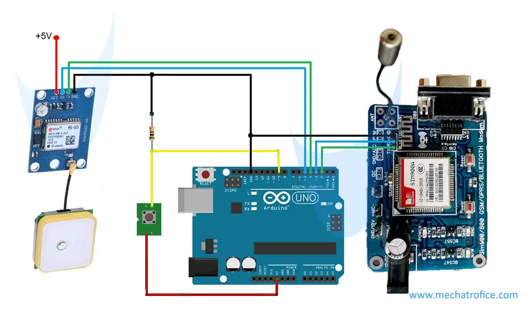
The main three components in this project are GPS (Global Positioning System) module, GSM Module, and an Arduino Uno. Here we are sending the live coordinates received by the GPS receiver module to a mobile phone via SMS using the GSM module.
GPS Receiver Module
A GPS receiver module is a device that receives information from GPS satellites and obtains the geographical position of the device.
GPS Module Arduino Connection
Pin configuration as in the below code and given circuit diagram.
| Arduino Pin | GPS Module Pin |
| Tx (Digital Pin 5 ) | Rx |
| Rx (Digital Pin 4) | Tx |
| GND | GND |
GSM Module
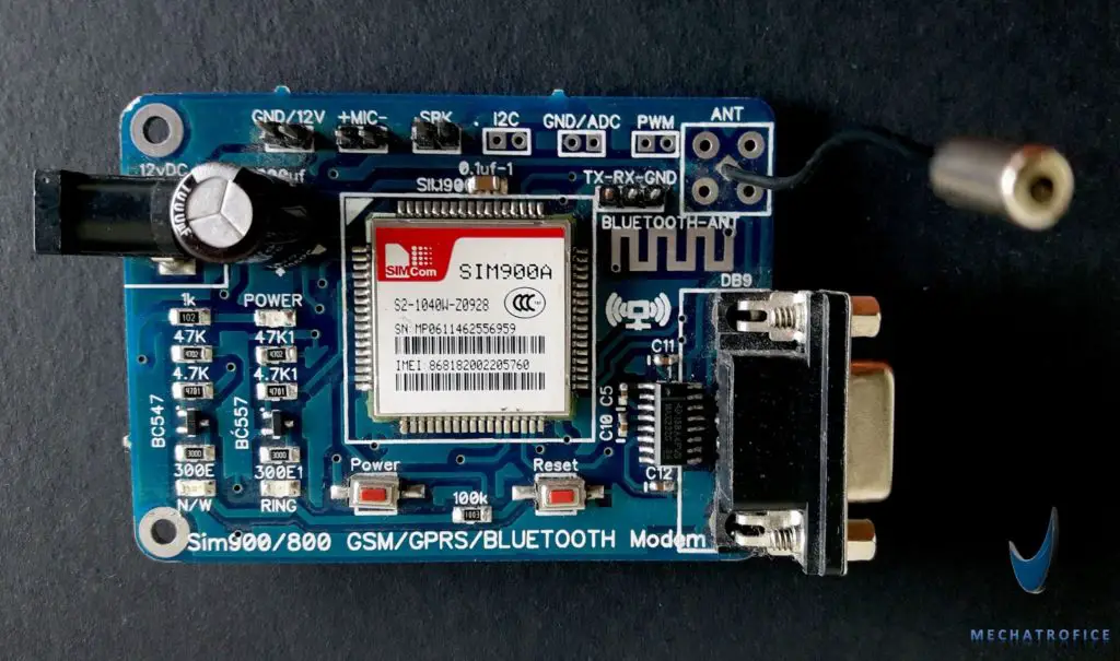
A GSM module is a device used to establish communication over a mobile network. GSM or GPRS Module requires a SIM card to operate or to register a connection with the network operator or service provider.
GSM module Connection with Arduino
| Arduino Pin | GSM Module Pin |
| Tx (Digital Pin 3) | Rx |
| Rx (Digital Pin 2) | Tx |
| GND | GND |
Refer the tutorial links given below for detailed working, codes, and interface of the GPS and GSM modules with Arduino.
- Interfacing sim800 / sim900A GSM module with Arduino.
- Interface and working of GPS receiver using Arduino.
The GPS receiver obtains the data as a whole NMEA format text. Only the latitude and longitude coordinates are taken from it; using the Arduino TinyGPS library. Then the GSM module sends SMS to the number specified in the code.
This code is useful for GPS and GSM projects like Vehicle Tracker and other Arduino based live location sharing or tracking devices, similar prototypes etc.
The switch input based GPS needs a manual action to operates or send SMS. It is to just send the location by ourselves. By just simple modifications the circuit can be integrated with a wide range of sensors to detect flame, vibration, or similar devices to automatically operates on specific events. Such as, using with a flame detector sensor to automatically send the location of the fire accident, vehicle accident detection system to send the location of accident vehicle to rescue team, etc…
Arduino code for sending GPS Longitude and Latitude coordinates on switch press.
#include <SoftwareSerial.h>
#include <TinyGPS.h>

int state = 0;
const int pin = 9;
float gpslat, gpslon;

TinyGPS gps;
SoftwareSerial sgps(4, 5);
SoftwareSerial sgsm(2, 3);

void setup()
{
  sgsm.begin(9600);
  sgps.begin(9600);
}

void loop()
{
sgps.listen();
  while (sgps.available())
  {
    int c = sgps.read();
    if (gps.encode(c))
    {
      gps.f_get_position(&gpslat, &gpslon);
    }
  }
    if (digitalRead(pin) == HIGH && state == 0) {
      sgsm.listen();
      sgsm.print("\r");
      delay(1000);
      sgsm.print("AT+CMGF=1\r");
      delay(1000);
      /*Replace XXXXXXXXXX to 10 digit mobile number &
        ZZ to 2 digit country code*/
      sgsm.print("AT+CMGS=\"+ZZXXXXXXXXXX\"\r");
      delay(1000);
      //The text of the message to be sent.
      sgsm.print("Latitude :");
      sgsm.println(gpslat, 6);
      sgsm.print("Longitude:");
      sgsm.println(gpslon, 6);
      delay(1000);
      sgsm.write(0x1A);
      delay(1000);
      state = 1;
    }
  if (digitalRead(pin) == LOW) {
      state = 0;
    }
      delay(100);
  }
If we need to track the location of a moving device from a distant place or monitor the position of an object at a regular interval of time it can be obtained by just removing the “if” condition to send SMS, instead just add time delay of few seconds or minutes. Then you can receive the current location of the receiver at fixed intervals.
To receive the SMS in a URL format to open directly on google maps the above message code can be replaced with,
      sgsm.print("https://www.google.com/maps/?q=");
      sgsm.print(gpslat, 6);
      sgsm.print(",");
      sgsm.print(gpslon, 6);
The resultant google map website address received as SMS will be, https://www.google.com/maps/?q=27.988139,86.924974 (GPS coordinate location @ ) which takes you directly to the map.
Arduino code for Sending GPS Location by SMS Request
#include <SoftwareSerial.h>
#include <TinyGPS.h>

float gpslat, gpslon;

TinyGPS gps;
SoftwareSerial sgps(4, 5);
SoftwareSerial sgsm(2, 3);

void setup()
{
  sgsm.begin(9600);
  sgps.begin(9600);
}
void loop()
{
sgps.listen();
  while (sgps.available())
  {
    int c = sgps.read();
    if (gps.encode(c))
    {
      gps.f_get_position(&gpslat, &gpslon);
    }
  }
sgsm.listen();
    if (sgsm.available() > 0) {
      String    c = sgsm.readString();
      c.trim();
      if (c.indexOf("GET-GPS") >= 0) {
        sgsm.print("\r");
        delay(1000);
        sgsm.print("AT+CMGF=1\r");
        delay(1000);
        /*Replace XXXXXXXXXX to 10 digit mobile number &
          ZZ to 2 digit country code*/
        sgsm.print("AT+CMGS=\"+ZZXXXXXXXXXX\"\r");
        delay(1000);
        //The text of the message to be sent.
        sgsm.print("Latitude :");
        sgsm.println(gpslat, 6);
        sgsm.print("Longitude:");
        sgsm.println(gpslon, 6);
        delay(1000);
        sgsm.write(0x1A);
        delay(1000);
      }
  delay(100);
    }
In the first code, the arduino checks the switch input to send the location. Here we have replaced the condition with a program to check the SMS received and send GPS location if the SMS contains the word “GET-GPS”. So by just sending an SMS with the text “GET-GPS” to the GSM module, the GPS location will be sent to the number specified in the code.
Which mobile sim should i use??
Either 2G or 3G or 4G Sim ??
For a SIM900 module, it is just 2G. The 3G, 4G sim works in it but just as 2G.
The sim should support 2G, it does not work with 4G SIM works on LTE and VOLTE only.
I’m using GSM A6 and it’s not working for me.
what should I add to the code?
A6 GSM work with 9600 baud rate but its default baud rate is 115200, so you can try at that rate also. Check whether the modules are working while using separately.
Hi Admin,
I want to ask that where we write the number to which we are sending the location.
Ah! I got it.
Sorry.
Hey admin …my neo 6m gps sends location throgh sim 900 gsm 000000 atitude and longitude ..what is the reason
Hey admin,
What if we want to send the location to multiple contacts.
http://mechatrofice.com/arduino/send-gps-location-via-sms#comment-12921
hi admin, how can i send gps location automatically to senders number who perform a gps location request?
The whole message text includes the sender number, date, time, message, etc. You can extract the sender number from the second field of the string and then use the number to send SMS.
hi admin, can you please type here the example codes for that. thank you
I’m building this but with a gsm 800l module would I do the same wiring? and how do you know the sim card is connected to the module and is working
By checking the blink of the network LED. It blinks every 3 seconds once the network is registered.
Refer : http://mechatrofice.com/arduino/gsm-send-sms
So I have the sim800l all wired up properly it just isn’t connecting to the Cellular network with the SIM card I’m using. What type of SIM card are you using? I also wanted to see how I were powering the gsm module in this Circuit the sim 800l needs its own battery pack to I added that and modified the Circuit you’re above thought I’m not sure it will still work
Pls I’m looking for help, don’t know what I have done wrong but the circuit is not sending the location to the number.. The arduino board dosent eve blink TX LED when the trigger button is pressed.
I’m new here.
Really thank you so much this code really works. whereas coding from other websites is not helping us and we gained some knowledge through this. We need one more help. we got latitude and longitude in a mobile phone using that how can I plot in a map automatically in a mobile phone.
It is described in the project how to receive the SMS in a URL format to plot directly on google maps. Did you mean something more?
hey Admin. I will replace the switch with 433mhz transmitter and receiver section is it possible..
Yes, you can. It is just an input, you can use or replace “if condition” with any triggerings like sensor thresholds, timer, values received via RF modules, etc.
shows like
2:21: error: TinyGPS.h: No such file or directory
compilation terminated.
exit status 1
TinyGPS.h: No such file or directory
Did you properly installed the TinyGPS Library? Follow the link in the article about Arduino GPS interfacing.
WHERE SHOULD I PASTE THE EXTRACTED COPY OF TINYGPS LIBRARY
Extract the zip to your library folder in your Arduino installation. Or add the ZIP file to Sketch –> Include Library –> Add.ZIP Library.
Download the TInyGPS Library
https://github.com/mikalhart/TinyGPS
Hi,
Instead of a switch can we get the GPS Coordinates by sending the sms to the tracker
Yes, you can. You need to add a code to check inbox SMS text.
can u send that code??
You can refer the “Arduino code for Sending GPS Location on SMS Request”.
Actually we are having ARDUINO MEGA , GPS , GSM MODULE. We tried our best with the following code.
SoftwareSerial sgps(4, 5);
SoftwareSerial sgsm(2, 3);
But we can’t get output in mobile. So could you please post the exact PINNUMBER which i can use in the code to get output in mobile.
Sir/Madam it is enough if you just edit and post the correct pin number
Try using pins,
SoftwareSerial sgps(10, 11); // RX, TX
SoftwareSerial sgsm(12, 13); // RX, TX
What is the value of the resistor used for the connection?Plss reply
It is a pull-down resistor its value can be around 1k-10K by the rule of thumb. 10k is a common selection.
Okk thankyou..Can we give 5v supply to gps module through arduino 5v pin.
Yes, it’s ok to power GPS from Arduino 5V. But for GSM external supply is required, because it needs some amperes.
Okk thankyou soo much..Really helped me alot..We got the output in terms of latitude and longitude …Still need to interface LCD to display messages like sms sent and also latitude and longitude….Please help how to modify the code for it…
Refer: Arduino LCD interface.
Use the above tutorial. Referening to that add an additional print line with lcd.print like the sgsm.print.
Instead of a switch can we get the GPS Coordinates by sending the sms to the tracker
yes, you can. Just need to add some code for receive and process the SMS.
hi sir, how i should do that, do you have something that I can refer to? My project same as yours but I dont wanna use switch. Please help me sir.
Just remove or replace the if condition to check the switch state. Could you explain more about your requirement?
why i am not getting anything on serial monitor
and sir i am using gsm sim800l evb,tiny gps and arduino uno
today is my project submission will you plzz help as fast as possible..plzz sir
If you are referring to the above code in this article, it has no code to display in the Arduino serial monitor. It used only software serial to receive data from the GPS module and Send the data via SMS through GSM.
If you are trying to display the serial data send and receive by these two modules, add “Serial.print” after every sgsm.print the same as it is used.
Refer : http://mechatrofice.com/arduino/arduino-serial-monitor-control
dear admin,
can you tell me how can i do this project with out pressing button?(send location)
thank you
Just remove the if condition “if (digitalRead(pin) == HIGH && state == 0)” or replace with some other conditions if you want to add something else. If removed, then the code starts to send location continuously. You can add extra time delay to send data at fixed intervals.
thank you admin for your kind reply.
dear admin,
i have get your second code(that send a sms and get location). i have followed your steps,and send as sms to my GSM module as you mention GET-GPS. but didn’t get reply.why is that?
thank you.
If that’s the case you have to debug each stage separately. Check whether the SMS is receiving, “GET-GPS” is available at serial and the module is sending SMS.
You can either use contact us form or admin@electric.mechatrofice.com
thank you admin
Which kind of Arduino were you using?
Arduino Uno
I exactly copied your code… But the led of tx doesn’t blink and I get nothing when I send an sms to the sim.
I’m using sim 800L , arduino uno and a gps neo6M… I can’t figure out where the problem is “knowing that both sim and gps are working perfectly when used separately”
Please help …
Add serial.print() and check whether up to what stage it is getting values.
Hi sir! Can you please show us the schematic diagram if we used sim800l and neo 6m instead of sim900? Thank you in advance sir.
There is no difference in the schematic diagram using a SIM800L instead of SIM900. Both are using same TTL serial communication using pins TX/RX. Connect the same digital pins used for SIM900 with arduino to the corresponding TX, RX, GND of SIM800L.
Refer the above link – Interfacing sim800 / sim900A GSM module with arduino.
Bro the code from sending location using sms is not working.
because, the gsm module dont recive any msg.
what can i do now plzzz help me in this regard.
Try with GSM and Arduino only.
Refer GSM Interface: http://mechatrofice.com/arduino/gsm-send-sms.
Admin can you send me the external power supply value and connection because gsm not connecting to network it blink every second and after some seconds it stops and then again repeating the process
The module requires a considerable amount of amperes, it may use up to 2A while transmitting the data, so use supply which has an ampere of 1.5-3A.
If you are using a GSM module with an inbuilt voltage regulator for the input of 12V, then use a 12V DC adapter (to 12V plug) or any 12V supply (to 12V pin). If the module has any 3.3V or 5V input pin then connect a supply of same voltage.
Admin, Does this code work for every sim network??
2G, 3G, and 4G sims work with the GSM module but the sim should support 2G. Because the module works as 2G.
It does not work with 4G SIM that works only on LTE and VOLTE.
Hi, does the code work well with sim800l, Ublox neo 6m gps module and Arduino uno? Or I need to make some modifications somewhere??
Yes, it does. For GSM module no library is using, only AT commands through software serial. And for the GPS we are using a TinyGPS library that is for modules using NMEA standard;neo6m uses NMEA standard. Hence, it would work.
Also, you can try with a TinyGPS++ library.
Can we send the message on regular intervals ?
means, send a location message on every hour / 30 minutes ?
Yes, you can. You need to remove the “if” condition and add a time delay. Then the SMS will be sent after every interval.
You can either use delay(), condition with millis() or an RTC (real-time clock) to set time duration.
Hi the code works the problem is whenever I add the software serial for the GPS the sending message function works but as for the receiving the module cant receive but i tried removing the serial number for gsm edited it with words if i receive GET-GPS i will print a certain word and it works. I wonder why It could send but cant receive. is it about baudrates?
“removing the serial number for the GPS i mean”. Asking about baudrate problems or pin problems?
Baud-Rate can be either 4800 or 9600, depending on your module type. Find the baud rate of your module.
Some times this type of issue might occur while using multiple modules at a time.
Try changing pins, Refer https://www.arduino.cc/en/Reference/softwareSerial.
I am using neo 7m is it compatible with the code you gave or should I buy a Neo 6m GPS?
Yes, it is compatible. Neo 7m supports GPS and GLONASS.
Here is the code i manually debugged the SendMessage() function works while the Receive doesn’t.
#include #include
float gpslat, gpslon;TinyGPS gps;
SoftwareSerial GPS(5, 6);SoftwareSerial SIM900A(10,11);
void setup(){
SIM900A.begin(9600);GPS.begin(9600);// Setting the baud rate of GSM Module
Serial.begin(9600);// Setting the baud rate of Serial Monitor (Arduino)Serial.begin(9600);
Serial.println (“SIM900A Ready”); delay(100);
Serial.println (“GPS Ready”);delay(100);
Serial.println (“Type s to send message or r to receive message”);
}void loop(){
while (GPS.available()){int c = GPS.read();
if (gps.encode(c)) {gps.f_get_position(&gpslat, &gpslon);}}
if (Serial.available()>0){
switch(Serial.read()){
case ‘s’:SendMessage(); break;
case ‘r’: RecieveMessage(); break; }
if (SIM900A.available()>0)
Serial.write(SIM900A.read());
}void SendMessage(){
Serial.println (“Sending Message”);
SIM900A.println(“AT+CMGF=1”); //Sets the GSM Module in Text Mode
delay(1000);
Serial.println (“Set SMS Number”);
SIM900A.println(“AT+CMGS=\”+639673894902\”\r”); //Mobile phone number to send message
delay(1000);
Serial.println (“Set SMS Content”);
SIM900A.println(“https://www.google.com/maps/?q=”);
// SIM900A.println(“latitude”);
SIM900A.println(gpslat, 6);
SIM900A.print(“,”);
//SIM900A.println(“longitude”);
SIM900A.println(gpslon, 6);
delay(100);
Serial.println (“Finish”);
SIM900A.println((char)26);// ASCII code of CTRL+Z
delay(1000);}
void RecieveMessage(){
SIM900A.println(“AT+CNMI=2,2,0,0,0”); // AT Command to receive a live SMS
delay(1000);
Serial.write (“Unread Message done”);
}
Did you try the code to send only, is that working? (code in the post to just send), without using the option to send – void SendMessage() and receive – void RecieveMessage().
I think the softwareserial of the GPS disables my Receiving function. Can I have an advice admin.?
Are you experiencing the issue with the receive, that is only with GSM SMS receive?
Hi im using arduino Mega 2560 i tried changing baudrates 4800 to 9600 my GPS type is Neo 7m. But what i get for both is all zero GPS(11,10) GSM(12,13)
Did you tried the GPS alone or used the GPS directly to serial monitor to check whether the module can receive data in NMEA text.
i am getting lat and long as ZERO in sms.i am using sim800l and neo 6m gps module
Did you get the right lat and long values on the serial monitor?
S I got it when gps is interfaced with arduino nano separately…but getting zero in sms when uploading this code …
Are you sure you are using the same code? Could u share the exact code?
no could not see anything
Hi, did you managed to fix it? I am getting the same thing. First, with a button I am getting the correct coordinates. Than I changed to trigger a message with sms, didn’t work. I changed the code a little, now I am getting a response, but with lat and long as just 000000. Is there a solution to fix it? Thank you
Maybe it is due to the issue with code. Could you share the modified code and circuit?
I am getting the same error. Did you fix it?
Good morning Admin.
Please I need the code that can send message with button pressed and when SMS is sent.
Secondly, why is the Rx LED on Ardiouno Uno not blinking to show it’s getting reception from the GPS module when I uploaded the code for button triggered for SMS.
I’m new to this, help me
Thank you..
use the code given under “Arduino code for sending GPS Longitude and Latitude coordinates on switch press”.
Rx will not blink when the GPS module gives a signal because it is not connected to default serial pins, RX & TX.
Arduino: 1.8.9 (Windows 7), Board: “Arduino/Genuino Uno”
C:\Users\user\Desktop\sketch_sep19a_LAS\sketch_sep19a_LAS.ino: In function ‘void loop()’:
sketch_sep19a_LAS:40:1: error: a function-definition is not allowed here before ‘{‘ token
{^sketch_sep19a_LAS:46:1: error: a function-definition is not allowed here before ‘{‘ token
{^sketch_sep19a_LAS:77:3: error: expected ‘}’ at end of input
} ^
exit status 1
a function-definition is not allowed here before ‘{‘ token
This report would have more information with
“Show verbose output during compilation”
option enabled in File -> Preferences.
It might be due to syntax error.
how can i programed with water level sensor for example if the water arose to specific percentage ex(30cm) then the action is “send the location” to the android application.
You mean to send via GSM or any other means of communication?
GSM or android application
This is my project idea it solves the sinking car+ drowning people.
How can I give you the details if you can help me?
The above code can be used for the GSM system with some modifications. Instead of triggering by a switch, use water level detection for triggering.
Refer: http://mechatrofice.com/arduino/automatic-irrigation-system (Just refer to switching once the water level reaches threshold).
my email is akhona.kaizer@gmail.com i tried to send you an email but seems like your email is incorrect
Email address is correct, I received your mail.
thank you sir I got your response
hey I am using sim800a and neo 6m
but I am not receiving back
I have used your code exactly
plz reply asp
Did you tried GSM and GPS modules separately with the Arduino and made sure both are working fine.
Is this a completed code or you are getting an error?
sorry sir I managed to fix the error, the problem was that I didn’t install library function for TinyGPS..thank you sir I really appreciate your time
Dear AKHONA,
can i get full code from you
can u please give the code without using a switch .
Just remove the switch from the circuit and the if condition, as briefed next to the first code.
I have tried but getting no sms can u please give me the whole code after changing?
please, leave your Email address.
Could you please give me the same full code?
Please give me full code
hi can you suggest me the best reliable gps module for tracking vehicles in india and also can we attach some sensor’s and relay to control thr ignition of the vehicle using your code ?
Neo series GPS modules (Neo 6m, 7m, m8..) are good options.
Yes, you can attach sensors and other control functions, the code and hardware need to modify according to your requirement.
Sir, I copied your exact code but on uploading to Arduino I am getting an error saying problem uploading to board. What could be the problem??
It might due to the connectivity issue between the IDE and Arduino board.
Refer:https://www.arduino.cc/en/guide/troubleshooting#toc1
Sir I tried copying this code exactly but I am not getting any SMS on my given number. Also while connecting the GPS and GSM modules to the Arduino as shown, the TX pin of the Arduino is not lighting up. So I connected as RX of gps-arduino pin 0, TX of gps- Arduino pin 1, RX of GSM – Arduino pin 10, TX of gsm- Arduino pin 9. Still not getting any sms. Could you please explain why?
Try, connecting GPS and GSM module as pin number given in tables. GSM – Arduino pin 3 TX, pin 2 RX. GPS – Arduino pin 5 TX, pin 4 RX.
Tried connecting as you said but I’m receiving latitude and longitude as 0.00 only. But it’s displaying correctly in the serial monitor
Try the GPS alone – http://mechatrofice.com/arduino/gps-latitude-longitude
Hi m using neo6 and atduino uno but not getting any sms or anything on the serial monitor
iam getting ????? in serial monitor….
iam using same code in nano
while iam checking gps before if condition iam getting ???? i tried with differet baud rates but not got thegps coordinates
Try the GPS module directly with any serial terminals and make sure it is receiving signals.
And also make sure that the Arduino serial communication is working fine.
Hello Admin,
Thank you for providing the code. Although code is working fine but one problem I am facing is that when ever I am clicking on the message it directly linked with my phone’s Google map and is showing my current location instead of message coordinate position. Please help
Thank you in advance.
Just change the default option on your phone. And try to open with any browser (or directly copy paste the link to URL bar).
Hi, can I use Arduino Nano for this? Or only Uno / Mega are usable?
No, you can use with any Arduino boards. But, the circuit connections and declared pin numbers, etc need to be modified in respect to the arrangement.
Should the sim inserted in the GSM Module should be recharged ?
It should be an active SIM card to register with the ISP. And need to be charged for SMS and call as per ISP charges.
Hlw, i am using GSM 800L module ..is it ok? because i am not getting any massage in my mobile.
GSM800L module is ok to use with arduino. Try the module directly with any serial monitors and make sure it is working fine.
Thank You very much Admin……
Your code really helped me alot……….
Hi sir, I would like to merge press button and sms request to send gps location when either press button or receive sms request. How can I merge all from your code above?
Thank you so much
you can combine both if condition with an ‘or’.
if ((condition1-switch press) || (condition2-sms request)) {
//send sms
}
how can i get gps location throught A6 gprs gsm module.Is that location also get to the mobile through SMS.
Yes, it works the same.
Thnx.
if we use node mcu,the above code is same or not
Same, but just note about the pin numbers.
thank you admin…..
can we use above code to send sms from mobile and get location back to that number. i’ll try but it doesn’t work.please can you help me
Your code gives me latitude and longitude of 0.000000 even though it is outside.
How will it send me the true coordinates of my location?
Check whether the GPS module is receiving the values by connecting directly to a serial monitor?
Hello sir! Good Morning! I would like to ask if you have schematic diagram or circuit for the “Arduino code for sending GPS Longitude and Latitude coordinates on switch press.” along with its resistor values if it has. Is it possible to ask for it and send it to my email? Thank you very much and I appreciate everything that you have done for this wonderful tutorial!
You can use a resistor of value 1K to 10K ohms.
Hello,
what is the best way to send a message from Arduino to register mobile and how to receive the message to turn off the particular thing which is attached to the Arduino board?
Can you please email me the process and required things to make this project successful and the mail id is rishinetha@gmail.com, thanking you.
sir/madam can i replace the switch with “Ultrasonic Distance Sensor (HC-SR04)” to get the same output ,please respond as soon as possible
thank you
Yes, you can.
Refer: http://mechatrofice.com/arduino/ultrasonic-distance-measurement
Thank you very much sir
Will you please send mi code using ultrasonic sensor . Please respond asap.
hi i am trying to use this for an 8th grade science project could you please tell me where to find the gsm module?
Most e-commerce sites, robot kits or hobby electronics shops, etc.
How to given power supply to the circuit and what is the volt rage
You can provide an external power supply because the GSM module requires a considerable amount of power. you can either connect a 12V supply to board 12V connector or 5V to 5V pins.
Sgsm doesn’t name type
It means no definition for that identifier visible to the compiler.
Did you have “#include SoftwareSerial.h” or properly declared sgsm ?
Can I use 800L GSM module
Yes, you can.
I have received sms to my phone….but it displays latitude 0.00000 and longitude0.00000
Iam using neo 6m gps
Please reply immediately
Check GPS separately and make sure you get the values in serial monitor.
You always get sms when you click switchbutton
Do you have any worked out code now. I also received zeroes as latitude and longitude values. If you have any code will u plzz share it?
I also got the same problem. When I used first method, it is works well. But, if I used second method, I received zeroes latitude and longitude. (Sorry for my bad English)
Me too bro what can i do?
i am using aurdino atmega 2560 .in this it consists of 4 tx ins and 4 rx pins so i can give the connections of gsm and gps module tx and rx pins to that instead of using digital pins
Not all pins in Mega 2560 support change interrupts.
Refer link in the comment: http://mechatrofice.com/arduino/send-gps-location-via-sms#comment-8041
same code for 800l GSM module and connection are also Same sir and also if I use 800l GSM module there will any problem with module sir
No problem, just make sure the input supply to the module and circuit connections are correct.
I have used your code but I am getting the co-ordinates as zero
Check GPS module separately.
Sir In my gps serial monitor nothing is not coming but position led is bilking for every one second plz help tomorrow is my project submission plz help
Try Gps directly to the serial monitor. Check baud rate, try alternate serial ports.
If I want to use a touch sensor instead of switch, how will the coding be? What changes do I need to do?
If you are using a Digital capacitive sensor touch switch then make no change to the code, just connect the output of the sensor to input pin 9. Because the output of a digital touch switch will be the same as a switch, HIGH state when touching and LOW state during no touch.
Or if you are using a piezo or similar component that generates an analog output then you can connect it to an analog pin and check if input reaches greater than a threshold value; if(A0 > thresoldvalue && state==0){…}.
Hi admin I’ve checked gps module separately but it’s working but if I will use the code above it returns 0 values when in print to serial monitor.
This is my initianilzation:
TinyGPS gps;
SoftwareSerial sgps(4, 3);
SoftwareSerial sgsm(7, 8);
my email is Lpagiwayan@gmail.com
Try adding sgps.listen() before sgps.available() and sgsm.listen() before sgsm.available().
Why the vcc of of gsm is not connected to anything and vcc of gps too
Because both modules are powered with external supplies, either 12V to its connector or +5V to pins. But all boards should have a common GND connection.
ok for now i want to give 5v to both gps and gsm.and resisotr one point is already connected to 5v pin of aurdino so how can i give it 5v to both gsm and gps
i tried to connect it to the 5v of arduino nano both gps and gsm are blinking but not sending the location and also im using a sim800l. also may i ask if what do you mean by external supply ?is it the battery? hope to answer we need because we will use it for our research subject
An external supply can be any DC power source, a battery, SMPS, etc. It should be able to supply enough amount of amperes that is required to power the GPS and GSM modules.
Can we use lm2596 and a dc adapter and a 9v battery for the sim800l gsm module or we can we can directly use lm2596 and 9v battery?Can you also give us a code sir?
If you are using an LM2596 DC-DC Buck Converter then you can use a dc adapter or a 9V battery as input to obtain a 5V output.
I use LM2596 DC-DC Buck Converter for sim800l, i connect the 5v of gsm to lm2595 and the gnd of gsm also….the gps and gsm are both blinking but when i press the switch it suppose to send message but it is not sending…i also try the gsm and gps if working individually and they are working individually…i hope you an give us a code and a circuit diagram if i use lm2596 to check 🙂
Use the same circuit but this time add an LED to any of the digital pins and insert the code to blink the LED inside in the “if” condition portion of the existing code as shown below,
…..
if (digitalRead(pin) == HIGH && state == 0) {
digitalWrite(6,HIGH); // eg:- Connect LED to pin 6
delay(1000);
digitalWrite(6,LOW);
sgsm.listen();
sgsm.print(“\r”);
…..
Then while operating the circuit press and hold the push switch till the LED blink once.
Also, make sure the input source of the buck converter is able to source more than 2 amperes of current.
What do you mean as all boards should have a common Gound, as you answered above?
If there’s external supply of V to GSM & GPS, then shouldn’t the Ground of GSM & GPS be connected to Ground of the external supply? If not to external supply, why to Arduino’s Ground?
The GND of both modules should be connected to the GND of external supply and Arduino. A common GND share GND of all power supplies.
For serial communication, the Rx and Tx of both modules are referenced with a logic ground. Hence a common GND with supplies is required to communicate modules that are powered by different sources.
can i connect the above circuit design gps and gsm and button to the same 5v pin slot of aurdino?
Modules draw a considerable amount of power; depending on the module type. Hence, both modules couldn’t get sufficient power if connected to arduino 5V pin and also it may damage the Arduino board. So it is better to use an external supply.
Both the modules are connected to external 5V supplies right?? not to Arduino’s 5V??
Yes.
I use 800l GSM module for above project but msg not coming and I also test separatrlybot GPS and 800l GSM there working properly but combination is not working properly plz help sir
Try adding sgps.listen() and sgsm.listen() before sgps.available() and sgsm.available() respectively.
Sir, I need code of interfacing of gps neo 6m
0-001 ,gsm900A , 16*2 lcd display, and ultrasonic sensor. Please help mi .
http://mechatrofice.com/arduino/lcd-matrix-interface
http://mechatrofice.com/arduino/ultrasonic-distance-measurement
I am working on project railway track crack detection vehicle but I am unable to interface GPS GSM and ultrasonic sensor . In this project ultrasonic sensor detect crack and coordinates of crack sent through message . Please sir help mi I have submittion.
http://mechatrofice.com/arduino/ultrasonic-distance-measurement
can i any one help me modify this code and add vibration sensor setting instead of switch
vibration sensor module is sw420
.Will you please send mi code for this project. Railway track crack detection vehicle in which ultrasonic sensor detect crack by not receiving echo and coordinates of crack are sent to registered number through GPS GSM I am using GSM sim900A, GPS neo 6M 0-001 .
Please sir help mi I have submittion and I am not getting code from anywhere.
You have to add additional lines for the ultrasonic distance measurement. Refer ultrasonic interface, http://mechatrofice.com/arduino/ultrasonic-distance-measurement ; integrate the code with the here code.
Replace the if condition in the code that checks the switch input state, with the ultrasonic output value to check if it is below the normal echo value.
if (ultrasonic_distance < normalvalue) { sgsm.print("\r"); .....
Sir, thanks for your response . Code is working but it shows error that “multiple libraries were found ” . With this it is generating file with the extension “.elf” instead of hex file . How can I fix it ??
Check your Arduino library folder if multiple library files are existing; previous versions or similar types.
Thanks very much. the code work perfectly well for me. I try to print the date and time along side the location but don’t know how to. Please I need your help.
Thanks once more
Hello sir, i already try the code that your given, it has no error,,but when i try it did not send the location to my mobile phone..i already try it separately . Sir can you help me..
Refer: How to send receive SMS from GSM modem using arduino; try the code and make sure it will be able to send SMS.
Hi, will this work if I use a sim800l?
Yes
I’m not getting the circuit diagram can any plz elaborate the connection plzzz
What changes should be made to use this code with a Standalone Atmega328p uc.
No change is required, use the same code.
I am getting lat and long as ZERO in SMS.I am using sim900l and neo 6m GPS module and nothing in serail mountor
and it shows user it own location
thank you this circuit is working thank you so much
Can you please help me with complete Arduino code that sends GPS location to an Android phone via Bluetooth Hc-42 module?
And is there any specific/suggested app I need to download in order to receive (or store) the code?
You can refer to these links.
https://create.arduino.cc/projecthub/sachendra003/temperature-monitoring-on-smartphone-937345
https://www.instructables.com/id/How-to-Read-Arduino-Sensor-Data-on-Android-App-Usi/
Change the codes so as to replace the serial values from the sensor with the GPS values.
hello sir, can i send those longitude and latitude to a web server using sim900 GPS/GPRS shield with Arduino
Yes with GPRS you can connect to a web server by TCP/IP protocol and send longitude and latitude values.
hello, i using arduino mega, gps and gsm module
but i cannot get the message in phone
hi sir, your code is running well, but i’m getting o.00000 values for both latitude and longitude, can i know how to fix it?
Check GPS separately. Make sure the variables have the values of GPS coordinates; try to print the values of the variables in the serial monitor.
how to write land phone caller id facility indicate Arduino programed pls help me
When I click bushbutton. I cannot receive sms always why
HI Sir
I want to send SMS with google link but I cannot receive SMS when I try your code2 .please send me coding for SMS with google link. Thankyou sir And I do not supersede your coding2 in your coding1.
Thank you
HI sir
please send me coding fully for SMS with Google map link?
Thank You
I can not understand your coding2 with Google map and what if the function is removed in coding 1.
Please explain to me.
The code with google map link is nothing but just adding the latitude and longitude coordinates to the URL of the map page, so the link will take you directly to the google maps showing the corresponding location for the latitude and longitude values you just received.
The only change in code with a google map link is the lines to print maps URL. Just add the lines for URL under the comment in the code //The text of the message to be sent.
Please help me to sending SMS to multiple recipients , on this program
How to sending SMS to multiple recipients ar same time
If you need to add an additional number, just repeat the code between lines “sgsm.print(“AT+CMGF=1\r”);” and “sgsm.write(0x1A);” with alternate number after the line “sgsm.write(0x1A);” in the current code.
Or if you need to send to multiple numbers, save the numbers to an array, number[] = {“AT+CMGS=\”+ZZXXXXXXXXXX\”\r”,…,”AT+CMGS=\”+ZZXXXXXXXXYY\”\r”}
then call number[0],number[1] using a for loop as sgsm.print(number[i]);.
After press switch , send message but not send location, only send 00000000.000000000 , location not send , wait i do sir
And i check my GPS module, its working in demo code , and gate location in serial monitor, in this program gps not work, only send 000000 in sms,
You are getting the GPS location in separate GPS code but not in code with GSM, right. Try to print GPS code in serial while using the GSM code and check whether you are getting any GPS values.
Can you share the exact code and circuit arrangement you have used?
I have not get latitude and longitude with google map.please explaun Sir
Are you getting the values without map url?
yes ,not getting in maps
how to make call and send massage on this code for 2 different number , and how to on auto reapply for send a massage in sim 800l and the sim800l also reapply a massage and location
Refer: http://mechatrofice.com/arduino/gsm-send-sms
Hi Sir. I have not get gogle map link with latitude and longitude in your second code.What wrong?please explain me .
This is important for my project.please
Could you share the exact code you are using, current output, the circuit arrangement.
Comment or mail to admin@mechatrofice.com
Sir i need some help , in my code , my code is run complete, but i also need some changes, so sir please help me out , i add some extra features in my code
Early day that you send conding me are the same
Try changing the pin numbers currently, you are using with alternate pins like,
SoftwareSerial sgps(10, 11); // RX, TX
SoftwareSerial sgsm(12, 13); // RX, TX
Try adding sgsm.listen() before sgsm.print(“\r”); and sgps.listen() before sgps.available() .
Ok sir i try
its my code , i press a switch it send a sms, sir plz edit me the code, for make a call , when i press switch , the gsm module make call in this number
void SendMessage1(){
digitalWrite(Buzzer,LOW);
mySerial.println(“AT+CMGF=1”); delay(1000); mySerial.println(“AT+CMGS=\”+919635838675\”\r”);
mySerial.println(“PLZ HELP ME: “);
mySerial.print(“LAT = “);
mySerial.println(flat,6);
mySerial.print(“LON = “);
mySerial.println(flon,6);
Add the below code just after sms code or if sms is not required replace sms code.
mySerial.println(“ATD+ZZXXXXXXXXXX;”); //ZZXXXXXXXXXX – number
delay(30000);
mySerial.println(“ATH”);
Thanks admin
Sir, the code above GSM and GPS, if you press a switch, the location will go. One thing I want to add to that CODE is what to do if someone calls GSM and the call is automatically received.
I try but do not get any message
Hi admin
Am using neo 6m n sim800l v1 am getting SMS with no coordinates: latitude: 0.000000 longitude: 0.000000 plz help
Did you check GPS and GSM separately?
Even I’m getting the same and I’ve checked gps and gsm separately . They both are working .what might be the problem .Have you resolved it
Am using sim900d i need to add for another platform how i do
Hello admin, How to use this data(locations) that we get and integrate it with cloud?
I want to store this location in cloud.
First, you have add an esp8266 wifi module(simple and ) or ethernet shield, GSM/GPRS module to connect the Arduino board with the internet.
Next, you can use any cloud based data logger to store data, like Arduino IoT cloud, and establish the connection.
Refer projects: https://create.arduino.cc/projecthub/jaume_miralles/publish-your-arduino-data-to-the-cloud-9dfaa2
https://www.instructables.com/id/Connecting-Arduino-WiFi-to-the-Cloud-Using-ESP8266/
hello sir,i have a problem when it comes to editing the code to add multiple numbers and receiving the coodinates in url format. Kindly help…. Thanks in advance
I wanted to ask I am using sim800l and neo 6m. Please I need the code for it. And also I want to ask for power supply recommendations. Please
You can use the same above code. The operating voltage of the SIM800L chip is 3.4V to 4.4V, you can power it externally or a common method used is connecting a diode in forward bias with the 5V supply. The diodes forward voltage drop reduces the 5V to around 4.3V; check the voltage with a dummy load before connecting to the module. You can power neo 6m with 3.3V or 5VDC of the Arduino.
Please have done it but the SMS is not sending. Please my country code is +234. And the number is about 14 characters. This is the number +2347036849881. Please I need the code. Thank you in advance and anticipation
Try GSM alone to check whether the SMS is sending, Refer: http://mechatrofice.com/arduino/gsm-send-sms
I have tried imtge GSM alone and it worked. Please help me with the complete code to send gps to SMS. Tried the one up it didn’t work
http://mechatrofice.com/arduino/send-gps-location-via-sms#comment-12954
tnx bro expellant work very help full good joy bast of luck
Thank you for your answers. Please on your last answer I am using Arduino nano. So I am using the connection like I saw in the code to send gps to SMS please I need the complete code to send gps to SMS. Thank you in advance
You can use the same code in the above post. Both nano and Uno are using atmega328, so the pin numbers are the same and the same code works in both.
Hello sir, i am using arduino nano for this project, should i change the pin? and delete the switch code.
I really need a coding for arduino nano interacting with gsm 900a to ask for gps .
which pin is connected to the rx tx?
You can use the same pins as in the circuit. If the switch code is removed then it keeps sending the SMS repeatedly.
hi sir just copy and paste 3 coding from above?
Sir can I use this program for Live location of my car
Yes, you can arrange to get the live GPS coordinates of the car.
hai, if i want to use arduino mega, is it pin for gps amd gsm still same, if it different, what the coding??
Refer comments: http://mechatrofice.com/arduino/send-gps-location-via-sms#comment-5845
http://mechatrofice.com/arduino/send-gps-location-via-sms#comment-11509
Sir please help me for final year project we are using sim 800l Neo 6m GPS module with piezo vibration sensor and the microcontroller is esp 32 and our requirements is to send Sms to numbers and the android application through firebase so how we integrate these modules and how we code these modules please help us sir we have just few days to submit this project sir if you don’t mind please send me detail about that through email.
Admin how to send GPS Location Via telegram using GSM module and nodemcu, GPS module?
Arduino: 1.8.13 (Windows 10), Board: “Arduino Uno”
Accident_Detector:2:10: fatal error: TinyGPS.h: No such file or directory
#include
^~~~~~~~~~~
compilation terminated.
exit status 1
TinyGPS.h: No such file or directory
This report would have more information with
“Show verbose output during compilation”
option enabled in File -> Preferences.
That is error
Install the TinyGPS.h library. Downlod and install it https://github.com/mikalhart/TinyGPS.
Refer :http://mechatrofice.com/arduino/gps-latitude-longitude
Can this program ran to nano? Is working or not
Yes, you can run this code in nano.
Where is the library
TinyGPS library: https://github.com/mikalhart/TinyGPS
Refer: GPS interface http://mechatrofice.com/arduino/gps-latitude-longitude
hi sir is it possible to combine the gps and the sim5320e into the same module ?
hi sir i am currently using a sim5320e and a gps can both this be combined to the same module as we want to minimize space if so what code should be change? do we need to be outdoors for the gps module to work? thx in advance
I am not sure whether any modules come with sim5320e and GPS. But a separate GSM 5320e and GPS can be interfaced using arduino.
If you need both GPS and GSM in a single module then go for a SIM808 Bluetooth Compatible GSM/GPRS/GPS Module or similar GSM+GPS modules.
GPS works indoors but it depends, you have to check that with the particular module you have.
If you need a compact arrangement modules like GSM+GPS A9G, A7, etc can be used.
bro i need code for sim808 for gps+gsm
Refer: https://github.com/blemasle/arduino-sim808
I used a limit switch but it doesn’t work. what I need to do
admin can we use this code for nodemcu esp8266 but i was havig sim808(gps+gsm) plz respond
Refer: https://github.com/blemasle/arduino-sim808
Sir, I test seperately both gsm and gps.
gps has value on serial monitor and the led was blinking. And gsm module can send, receive sms and the signal is good. but if i run it together I can’t get any reply from the module. I also used a sufficient power supply for gsm module. Also it was perfectly work on switch press. But i was having a problem when it comes to sms request. What should I do Sir ? Thank you..
if that the case, print the string c in the serial monitor which is “String c = sgsm.readString();” and check whether you are properly receiving the SMS and it has a text “GET-GPS”.
Tried to read string c. but i havent seen any data on serial monitor.
Serial.println(c);
That means you are not receiving the SMS.
Try adding below two lines after sgsm.listen();,
serial.println(“AT+CMGF=1\r”);
serial.println(“AT+CMGR=1\r”);//Read SMS at location 1.
If the above two line not working try this lines instead,
serial.println(“AT+CMGF=1\r”);
serial.println(“AT+CNMI=2,2,0,0,0\r”);
Refer: http://mechatrofice.com/arduino/gsm-send-sms (Receive SMS using GSM module) Try with the code only for receive SMS.
Sir i already do that, seperately and it can send “HELLO WORLD” like in the example, and i receive messages. by the way sir I use sim800L
sir after i add this code begore sgsm.listen()
serial.println(“AT+CMGF=1\r”);
serial.println(“AT+CMGR=1\r”);
it is now sending gps location. but my problem now is it has no value
lat. 00000000 long 0000000000
my gps is working and the led is blinking. If i test it separate it has value in serial monitor.
I also try to change the connection. instead of software serial. I use the Rx-Tx connection of arduino to Gsm module. and it sends me the gps location with value. but the problem is it sends me gps location every 30secs without texting “GET-GPS
Sir I really need your help. i am working with it for the past 3 days. but still cant figure out where is the problem.
Use the same code used in the article to send SMS on request. But this time remove the GPS code completely and send some text.
Just to check that whenever you send “GET-GPS ” the circuit can send any SMS.
Hi sir, i also got 0 coordinates and on the serial monitor it also shows 0 but the gps module is blinking just fine. I tested it seperately and the gps gives coordinates on the serial monitor but when combined with gsm the coordinates just come up as 0. Any advice you can give to help me sir?
You have to troubleshoot by changing RX/TX pins, checking the power supply source – whether it can deliver power for both modules at a time, disabling separate parts of the code, etc.
I finally got it. Thank you so much sir!
Hi Shash how do you fix it? Can you share it with i have the same problem. Can you share the code and schematic. Thanks
what modules did you use fo the SMS/GPS?
SIM900A GSM module & SIM28M GPS module(or NEO-6M).
hi sir, i have this project that requires arduino nano, gps, gsm, pulse sensor 433 MHZ RF Transmitter and Receiver and Battery. the system should make a buzzer sound once the button is pressed on and then send current location and current pulse rate to the registered number. the system is divided into two parts, the transmitter part: 433 MHz RF transmitter and SOS button, when button is pressed a buzzer sound will be generated in the receiver part which consist of 433 MHz RF receiver, arduino nano, gps, gsm and pulse sensor. the data will be sent from transmitter part to receiver wirelessly and allow to send current location and current pulse rate to the registered number. can you help me with the code or how to connect the circuit. thank you
Refer to the code: http://mechatrofice.com/arduino/rf-remote-controller-using-arduino-and-ask-module; Modify the code in this article by removing the part of data to “off”, so when the switch is pressed it sends a switch ON message.
At the receiver part, under the action of switch ON use the above code in this article to get the GPS data and send it via GSM. Along with latitude and longitude, you can add sgsm.print(“Pulse”) or the data of pulse rate.
thank you so much, but what do you mean by removing the part of data to “off” ?. Do you mean to remove the switch_off in the code ?
Yes, because you only need to repeat a single action.
so for the Transmitter code should be like this right:
#include
#include
const int switch_on = 2;
int state = 0;
char *msg;
RH_ASK driver;
void setup()
{
driver.init();
pinMode(switch_on, INPUT);
}
void loop()
{
if (digitalRead(switch_on) == HIGH) {
msg = “Switch_ON”;
state = 1;
}
else if (state == 1) {
driver.send((uint8_t *)msg, strlen(msg));
driver.waitPacketSent();
delay(200);
state = 0;
}
}
Yes, but as swith off is not required, inside the void loop below code is enough,
if (digitalRead(switch_on) == HIGH) {
msg = “Switch_ON”;
driver.send((uint8_t *)msg, strlen(msg));
driver.waitPacketSent();
delay(200);
}
do i need to use two Arduino. One with the transmitter part and the other one with the receiver part, or do i just use only one Arduino Nano in the receiver part ?
because as the link you told me to refer to, it uses two Arduino. but the project i am working on only requires one Arduino in the receiver part . do you think i should add an Arduino in the transmitter part or not. I’m not sure, can you advise me i would appreciate it.
Yes, you need two Arduinos as per the given method. Because the transmitter and receiver need an Arduino to run the TX and RX sketch as it is using an ASK library. If need to do without Arduino then you can use the ASK itself without a library but the chance of error is high. Or you can use another module or a single channel RF remote.
Hello, im using an SIM800L it is the same code for the SIM900?
Yes, it could work with this code, if you have any specific module look for the AT commands. Because the Arduino is communicating with the GSM modules by just using the AT commands.
awesome, thanks.
Do i need to remove the button to make the sms request function work ?
The code for SMS requests has nothing to read about the button input so it is not required and it has no effect on that circuit or code. But even if you leave with the button input as in the circuit it has no issue with working.
The Button Circuit and Code is perfectly working but if i try the sms receive code i dont even get an sms
Separately check the code to receive the SMS and make sure you are receiving the text “GET-GPS”; use the serial monitor to print the string.
Sir how to use above code with haversine formula
Refer: https://community.esri.com/t5/coordinate-reference-systems/distance-on-a-sphere-the-haversine-formula/ba-p/902128
Hi Sir, both gps and sim80p modules are working. But cant either recieved proper coordinates. How can I fix this. I tried everything. Thank’s
Can’t receive proper coordinates mean garbage values, wrong values, or coordinates that are not accurate?
Im using sim800l ive tried to use you code but it doesn’t work. How can I fix this. Can you send me a working code. mindermannjanpiere@gmail.com thanks
Hi. We have uploaded the code . There were no errors but we are not getting any output .where is the mistake .Admin please help me .
Hi! I’m doing a project in which I want to connect a GPS locator to my phone, or build a device with an Arduino nano that remotely sends a signal from my location to a second device every time the button on device 2 is pressed. The second device It will be connected to an LCD screen and instead of reproducing the data of my location, that makes the conversion for example to: The subject is X meters from here (example that makes the calculation of how much is device 1 from device 2 and appears on the screen when you press the button). Its viable? What kind of software / tools would I have to use to create this connection remotely? Can the data be transformed so that it does the calculation that I have commented in the example? Thanks.
A simple method you can use is an RF module to send data, Refer: http://mechatrofice.com/arduino/send-values-wirelessly-using-rf-module
Also, the distance can be calculated without any special tools/software by using simple formulas to calculate the shortest distance between two coordinates. But overall accuracy in this type of project will be poor, so it needs to be tested and calibrated.
Hii admin, I’m doing a project on tracking the live location of passenger if an accident oocurs ..
how can I implement in coding side and what components should i used ??
please reply
After press switch , send message but not send location, only send 00000000.000000000 , location not send , wait i do sir and i aslo check my GPS module, its working in demo code , and gate location in serial monitor, in this program gps not work, only send 000000 in sms.
Hi admin .I’m getting location but only 00.000000 is coming .Both gps and gsm are working fine individually .what should I do now
Hi Admin,
I’m making a project to make a autonomous RC plane. So far the plan is to include GSM/GPS module to my arduino with gryoscope/accelerometer sensor. Will be sending/receiving data to the arduino through GSM module to have a monitor over the flight behavior. Also will I be able manually override the plane i.e to control the wing movements of the plane thru by sending data to gsm module–>arduino–>actuators, what will be the delay impact?
I will give a flight path coordinates and would be expecting the plane to follow the path using PID control.
If you have any suggestions please let me know. Really excited to do this.
Sending data, you mean to use the GPRS of the GSM module? An RF control might be the better option.
Yes, the RC can obtain the direction from the flight path coordinates and navigate with the help of a compass module.
Hi Admin,
The plan is to control the plane using my phone through Blynk app. I think it would be better to use a NEO6M GPS module, with an esp32 wifi module. I not yet sure about the range of the WiFi module, but this is what I’ve improved with my idea so far. Please help me with more suggestions.
Thank you!
Tushar
I don’t think wifi is a good option for your application since it is an RC plane. Better go for RF modules with enough range like modules of Lora, XBee, NRF with antenna, etc.
ok sir, thank you so much!!
also will I be able to interface the above modules like LoRa , NRF with my android phone in anyway ?
Yes, you will be able to interface similar modules with an android phone via a microcontroller connected through Bluetooth or wifi. But the performance and functional quality is hard to predict, it can be found only by testing the circuit as a whole.
Hi Admin, the code only works when I disable one of the module in the code seems I can’t use them simultaneously
Did you check the external power supply, that it has enough power to work with both modules simultaneously?
Hi admin, i’m doing the project that have to send coordinates to a desktop system using GSM SIM800C, NEO 6M GPS MODULE and ATMEGA328, how can i make it,,, your help pls because i have tried different ways but the gps didn’t light up
If the GPS is not lighting up then it might due to poor signal, try it outdoor and try changing the position of the antenna.
To send coordinates to a desktop system you can receive the SMS to an Arduino circuit connected with a GSM module, then the data can be read via the serial monitor, wifi, Bluetooth, or internet (if the GPS device has GPRS connectivity then the coordinates can be directly shared to the desktop via the internet without sending SMS).
Hi admin. Please tell me name of gps module and controller name
hey admin, can you please look at my code once. individually components are working but when I’m using them all together then no response. Here I’m using two ultrasonic sensor, rain sensor, buzzer, neo 6m, sim900a, switch button and arduino uno.
Is arduino sufficient to power all components or I need to give external supply to some components. Thank you.
#include
SoftwareSerial gpsSerial(9,10);
SoftwareSerial gsmSerial(7, 8);
TinyGPS gps;
int buttonPin = 11;
const int buzzPin = 6, rain = A4;
const int echoPin1 = 2, trigPin1 = 3;
const int echoPin2 = 4, trigPin2 = 5;
long duration1, duration2;
int distance1, distance2;
int state = 0;
float lat, lng;
void setup()
{
pinMode(trigPin1, OUTPUT);
pinMode(echoPin1, INPUT);
pinMode(trigPin2, OUTPUT);
pinMode(echoPin2, INPUT);
pinMode(buzzPin, OUTPUT);
pinMode(rain, INPUT);
digitalWrite(buzzPin, LOW);
Serial.begin(9600);
delay(100);
gpsSerial.begin(9600);
delay(100);
gsmSerial.begin(9600);
delay(100);
Serial.println(“System is getting ready.”);
}
void loop()
{
distancecheck();
buzzercheck();
SendMessage();
}
void distancecheck()
{
digitalWrite(trigPin1, LOW);
delayMicroseconds(2);
digitalWrite(trigPin1, HIGH);
delayMicroseconds(10);
digitalWrite(trigPin1, LOW);
digitalWrite(trigPin2, LOW);
delayMicroseconds(2);
digitalWrite(trigPin2, HIGH);
delayMicroseconds(10);
digitalWrite(trigPin2, LOW);
duration1 = pulseIn(echoPin1, HIGH);
distance1 = duration1 * 0.0175;
duration2 = pulseIn(echoPin2, HIGH);
distance2 = duration2 * 0.0175;
Serial.println(“Distance1: “);
Serial.println(distance1);
Serial.println(“Distance2: “);
Serial.println(distance2);
}
void buzzercheck()
{
if (distance1 <= 500 || distance2 <= 500 || digitalRead(rain) == HIGH)
digitalWrite(buzzPin, HIGH);
else
digitalWrite(buzzPin, LOW);
}
void SendMessage()
{
gpsSerial.listen();
while (gpsSerial.available())
{
int c = gpsSerial.read();
if (gps.encode(c))
gps.f_get_position(&lat, &lng);
}
if (digitalRead(buttonPin) == HIGH && state == 0)
{
Serial.println("BUTTON PRESSED");
gsmSerial.listen();
gsmSerial.print("\r");
delay(1000);
gsmSerial.println("AT+CMGF = 1\r");
delay(1000);
gsmSerial.println("AT+CMGS = \"+91xxxxxxxxxx\"\r");
delay(1000);
gsmSerial.println("IT'S AN EMERGENCY, NEED HELP. MY LOCATION IS: ");
//https://maps.google.com/?q=12.905488,77.519113
gsmSerial.print("https://maps.google.com/?q=");
gsmSerial.print(lat, 6);
gsmSerial.print(",");
gsmSerial.println(lng, 6);
delay(1000);
gsmSerial.write(0x1A);
delay(100);
state = 1;
}
if (digitalRead(buttonPin) == LOW)
state = 0;
}
You need an external power supply, because modules like sim9000a GSM requires considerable amount of amperes. So use an external supply and provide a common GND connection.
Hi admin ,
how to add Ultrasonic sensor to this project , i just want give buzzer info after the object detected , can u please include the ultrasonic sensor code and send
thanks a lot ..
you can refer similar examples in, http://mechatrofice.com/arduino/ultrasonic-distance-measurement, and circuit & codes in http://mechatrofice.com/tag/ultrasonic-sensor.
SIR IM GETTING MY LOACTION AS 0,0 WHAT IS THE MISTAKE
Check GPS receiver values or the values of latitude and longitude variables.
Admin sir if you don’t mine can you please send the code with the replace of switch with 433 MHZ Transmitter ND reciever with RF IC boards and the output from RF RECIVER is connected to ARUDINO uno and which it is connected to GPS module and GSm module. When button is rf Ic board(transmitter) .there is signal transmitted to rf Ic board(reciver) which is connected with help of jumper wire from RECIVER to arduino uno which get location and transmitted to phone number using GSM module. Pls sir Pls sir waiting eagerly for your reply.. Thank you sir for this opportunity.
Please check the email sent to your address.
Hi admin. I am getting location as 0,0 .can you please let me know what the issue .pls solve this issue.
can i use this code with dragino lora shield too? if i can, can you tell me what part i suppose to edit? pls reply, thanks admin
If you have to add Lora with this project you have to include the additional library for Lora and need to add its functions in the code as a whole.
hi admin, thanks for the tutorial. but i have the problem. i don’t get the reply from the module gsm. im using arduino uno, sim900a, and dragino shield lora. i have the project about lora. module gps work with the lora (another device) and send the location to module gsm with lora device too. but i don’t get the reply from module gsm. please help, many thanks
Hi sr, could it be possible for it to be triggered both in the switch, and sending sms request for gps location but only in one arduino? or do I need separate arduino for the both to function?
You can do both switch triggering and sending SMS with a single Arduino.
Can you show how? Thank you
The code for GPS receiver and sending SMS is the same in both codes the only difference is the triggering. So by just adding two separate conditions to check, both types of triggering can be used.
I don’t how to add the code can you give me an example please
Try the below code, here the code to send SMS is defined as a function with name sendsms(). Then it can be called for both separate triggerings; switch and sms request.
void loop(){ sgps.listen(); while (sgps.available()) { int c = sgps.read(); if (gps.encode(c)) { gps.f_get_position(&gpslat, &gpslon); } } // if condition to check switch press if (digitalRead(pin) == HIGH && state == 0) { sendsms(); // call function if push switch is pressed. state = 1; } if (digitalRead(pin) == LOW) { state = 0; } // if condition to check SMS request sgsm.listen(); if (sgsm.available() > 0) { String c = sgsm.readString(); c.trim(); if (c.indexOf("GET-GPS") >= 0) { sendsms(); // call function if SMS request is true. } } //Add code to send SMS as a function. void sendsms() { sgsm.listen(); sgsm.print("\r"); delay(1000); sgsm.print("AT+CMGF=1\r"); delay(1000); /*Replace XXXXXXXXXX to 10 digit mobile number & ZZ to 2 digit country code*/ sgsm.print("AT+CMGS=\"+ZZXXXXXXXXXX\"\r"); delay(1000); //The text of the message to be sent. sgsm.print("Latitude :"); sgsm.println(gpslat, 6); sgsm.print("Longitude:"); sgsm.println(gpslon, 6); delay(1000); sgsm.write(0x1A); delay(1000); }It says that the ‘pin’ was not declared
It mark on
if (digitalRead(pin)==LOW)
You should define a digital pin; add before void setup,
const int pin = 9; // variable “pin” as digital pin 9.
still the long and lat is 00,00 even the gps are working
Please try troubleshooting through the methods mentioned in the comments.
the sms request not working only the triggering button
how to loop a text message every 5 minutes using the first program above?
Use the below methods to send SMS every 5 minutes.
if((millis() – last) == 300000){
last=millis();
//Add code to send SMS here.
}
how about sending multiple contact in one click of push button.
can you change the original triggering code below. atleast minimum 5 contact number.
thank you admin
Repeat lines to send SMS with new numbers.
Or store numbers in an array and use a loop function to send SMS for each number.
Refer : http://mechatrofice.com/arduino/gsm-send-sms#comment-14213
https://www.google.com/maps/?q=27.988139,86.924974 <— this works when I used Maps for Browser but when I used Google Maps Apps(Android), it doesn't appear anything. What's the solution?
In google maps, you can enter latitude and longitude in the search box like 27.988139,86.924974.
Hi admin, can I use other modules for this like the sim900?
yes, you can.
good day sir. in the gps there is 5v may i ask where it is suppose to connect and what “if condition” should be remove. is it the last part of the code or the in the upper part of the code where that code is if (gps.encode(c))
{
gps.f_get_position(&gpslat, &gpslon);
}
}
if (digitalRead(pin) == HIGH && state == 0) {
sgsm.listen();
sgsm.print(“\r”);
delay(1000);
sgsm.print(“AT+CMGF=1\r”);
delay(1000);
hope you answer 🙂
Connect to a power source of +5V with the GND connected in common. The if condition to alter the triggering is the last one that is “if (digitalRead(pin) == HIGH && state == 0)”.
Hi, when sending Google Maps coordinates as follows:
[code]
sgps.print(“http://maps.google.com/maps?q=”);
sgps.println(gpslat);
sgps.print(‘,’);
sgps.println(gpslon);
[/code]
then an sms is received with url as follows:
https://maps.google.com/maps?q=51.201694 but the longitude appears outside the url link: first a comma then the longitude.
How can the longitude be made part of the url link?
Thanks a lot!
Erik
Check for any space or hidden characters between the text, if any try removing them.
Solved: your Google Maps command should be changed to
sgps.print(“https://www.google.com/maps/search/?api=1&query=”);
sgps.print(gpslat, 6);
sgps.print(‘,’);
sgps.print(gpslon, 6);
Thank you 👍 for your suggestion.
Hi, can you please help me admin, my gps just sends 0.000000 latitude and longitude locations. I already checked that the gps is working fine with other codes.
Will it work with SIM 800L
Yes, it works.
The same code ??
Hello sir can I use sim800A & is it work with same code?
Yes, it works.
hey admin.. what if i used ultrasonic sensor as trigger to send gps coordinates using gsm simm800L
No problem, you can use any triggering method. It will work.
hiii sir, Vcc of GPS module should be connected to 5v power supply? and please give me the link to check whether GPS and GSM interfaced with Arduino Uno are working individually or not?
Available links are given in the article just above the given circuit arrangement, please refer to it.
I’m using Sim800L EVB is this works fine or not? and if you have source code for using sim800L evb can you kindly send a link much appreciate
Hello sir, We are using MQ-3 sensor for detecting alcohol in our project. So we want to connect sensor to this circuit. So I want to know that which changes we have to do in circuit and code ?
Replace the “if condition” to check the switch press with the sensor output, so as to compare the threshold value for analog input or a boolean logic to detect the HIGH or LOW state for digital input.
Replace the push button pin with the MQ-3 sensor output.
Hi admin i am using gsm gprs sim800a 4g LTE module all are fine but not sending sms in the module please tell me what is the problem and send me the code for any different for SIM800A module
There could be several reasons why the SIM800A module is not sending SMS messages. Some common issues include:
Incorrect configuration of the module: Make sure that you have configured the module properly with the correct APN, PIN, and other settings.
Insufficient balance or credit on the SIM card: Make sure that you have sufficient balance or credit on the SIM card to send SMS messages.
SIM card not activated or blocked: If the SIM card is not activated or has been blocked, it will not be able to send SMS messages.
Incorrect AT commands: Make sure that you are using the correct AT commands to send SMS messages with the SIM800A module.
Try this sample code to send SMS using the SIM800A module and make sure the SMS sending is working fine:
#include SoftwareSerial.h // include the SoftwareSerial library

SoftwareSerial SIM800A(7, 8); // create a SoftwareSerial object to communicate with the SIM800A module

void setup() {
SIM800A.begin(9600); // start the SIM800A serial communication at 9600 baud rate
sendSMS(); // call the sendSMS function
}

void loop() {
// loop function is empty
}

void sendSMS() {
SIM800A.println("AT+CMGF=1"); // set the SMS mode to text
delay(1000);
SIM800A.println("AT+CMGS="+1234567890""); // set the destination phone number
delay(1000);
SIM800A.println("This is a test SMS message."); // set the SMS message
SIM800A.println((char)26); // send the SMS message
delay(1000);
}
Note: Make sure to replace the destination phone number with the actual phone number that you want to send the SMS to. You may also need to adjust the delay times based on your specific setup.
Hii Admin
If i want to add a fingerprint to it how can i do that .Like instead of push button on every fingerprint sense a message has to be send.will you plzz help me with this
In the same arrangement only thing you have to replace is the “if” condition that checks the push button state, replace it with a fingerprint to verify state is TRUE or FALSE.
Hi admin, when I pressed the button I only receive 0.000000 in both lat and lon in sms not my actual location, I already test my gps neo6m and my coordinates reflected in the serial monitor but when I use your code above I only get 0.0000000, is there any solution for this? thank a lot admin
Probably you should use another “gps code” to activate your gps until it blinks after it does go to this code and run the code
Bonjour, comment fusionner les deux codes svp?
i have done his iam getting location that i have mentioned …. when i pressed the button i am getting location but same mobile location is sending via msg to same mobile