Arduino voltage controlled oscillator (VCO)
A voltage controlled oscillator or VCO is an oscillator circuit which generates a signal with a frequency value varies with the instantaneous input voltage.
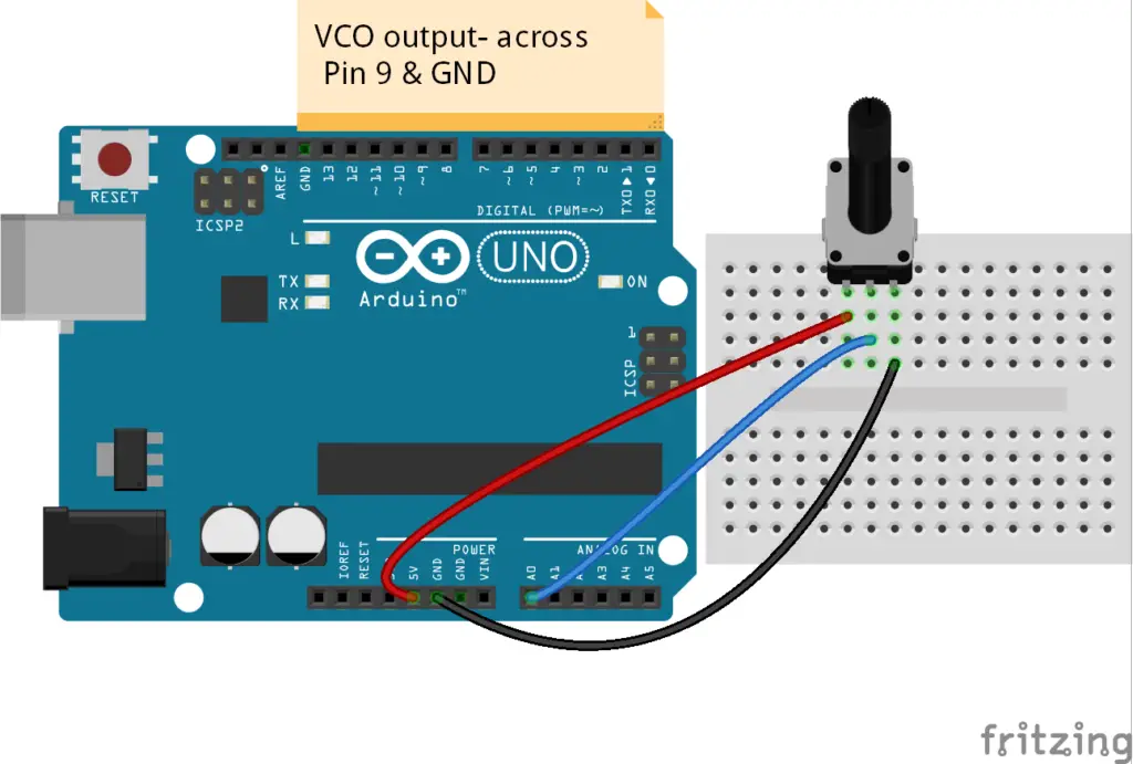
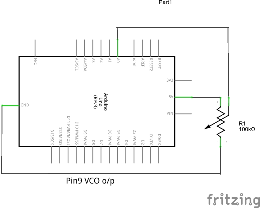
In this VCO, the Analogread pin A0 is connected to wiper pin of the potentiometer. The terminal T1 of the potentiometer is connected to the 5V pin and the other terminal T2 to the GND.
The value of variable “frequencyinput” is read from the analog read input. Its value will be in the range of 0 to 1023 and it is mapped to 50 to 5000 range.
The mapping range can be varied in the limit of minimum 31HZ and maximum 65535HZ frequencies of tone function.
 With respect to the value of “frequencyinput” (which is a function of the input voltage), the tone function generates an output at pin9. So by turning the knob or varying the input voltage, the frequency of the output can be changed accordingly.
Arduino Vco Code
void setup() {
  pinMode(9, OUTPUT);
}

void loop() {

  int frequencyinput = analogRead(A0);
  frequencyinput = map(frequencyinput, 0, 1203, 50, 5000);
  tone(9, frequencyinput);
  delay(100);
}
how do you convert this into sound?
I’d like to take the voltage and use it to drive, say, a VCO…
You just need to connect a low power speaker directly between the output pin and GND. Or you can use a high power speaker with an amplifier circuit; while using such external circuits make sure it has proper isolation with the Arduino board by using optocouplers, buffer circuits, etc. Also, you can set the frequency limit between audible range using map function in the code.
what is the output pin?
how can i add control voltage at 1v/oct?
Using the map function in the code you will obtain a linear function of frequency with respect to the input voltage, hz/V. For v/oct, you can scale the input voltage to a voltage range and then use a function to obtain the frequency function, frequency = f(x).
Ola Gerome, tudo bem? Conseguiu resolver a questão do controle 1v/oct?
Thank you very much for your explanation! I love this website’s content!
Could you please – if it is not too time consuming – may give us a short code example (ideally for v/oct)? Thank you very much in advance!
Best regards,
Michael
Is it possible to create different waveforms?
Yes, it is possible to generate a kind of different waveforms by pulse width modulation. It is by using wave equations to generate instantaneous values for analogwrite function. Along with some passive components, you can improve the wave shape.
Or use the circuits to convert square wave or PWM output to other waveforms.
is there any code available to allow in this sketch, the pulse width to be varied from , say 5% to 95% using map function.