How to Wire a Switch Box ? Electrical Switch Board Connection
Switch box wiring or switchboard wiring is a common wiring arrangement used in most house electrical wirings or switchboards. The given circuit is a basic switchboard wiring for a light switch (one lamp controlled by one switch) and 3 pin plug socket with control switch.
How to wire up a switchboard
In the below wiring diagram, the phase line is connected parallel to the light switch and the plug socket switch. Here, one pole of the both SPST (single pole single throw) switches s1 & s2 are connected to the phase line of the supply. The other pole of switch S1 is connected to the lamp and the other pole of switch S2 is connected to the phase pole of the three-pin socket.
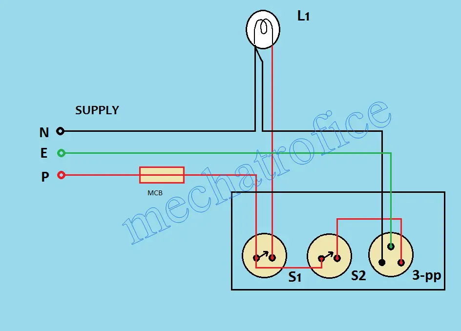
The earth line is connected to the earth pole of the socket and the neutral line is commonly distributed to the lamp and neutral pole of the socket.
Here only one lamp is connected from the switch box. The number of loads can be extended by adding more loads in parallel to the lamp. But, the wiring capacity and rating of components should be considered while adding more loads in parallel. For the independent control of additional loads, connect the loads directly from the phase through another switch.
Switch box wiring components required
| Component | specification | Quantity |
|---|---|---|
| MCB | 250V , 50Hz , 5A | 1 |
| Switch | SPST, 250V, 5A | 2 |
| Lamp | 230V | 1 |
| 3 pin socket | 230V , 5A | 1 |
Power point wiring diagram
A power point wiring has a circuit similar to a normal 3 pin socket connection with switch control. But unlike a normal electrical outlet wiring, power outlet connections are taken directly from the main distribution box. Also, it shares no parallel connections with the phase or neutral from other loads or sockets.
A simple electrical outlet is an extension connection taken from a nearby phase, neutral, earth poles. Sometimes 3 core wires are used for such connections. But in a power point wiring, three core wires are not generally used for wiring. Single-core multi-strand wires mainly with copper are used for the connection. Because, usually power points are used to operate high power rated devices with heavy loads such as compressors, heaters, inverters, UPS, etc.
Earthing is very important for a power point box. Because it is essential for the safety and to prevent shock from the metallic body or open contacts of the devices.

The circuit arrangement is very simple to wire. The neutral and earth line from the DB is connected directly to the respective ‘N’ and ‘E’ poles of the socket. The phase line is connected to pole ‘P’ through an SPST switch.
To make the wiring easy and to avoid wrong connections, it is better to label the ends of the wires. Also, a standard colour code can be followed for choosing the wire colours.
Below table has a common standard colour code of wires followed for power plug connections.
| Colour | Connection |
| Green | Earth |
| Black | Neutral |
| Red | Phase |
3-pin Plug and Socket wiring circuit diagram
Plug and socket are electrical devices used to connect the electric supply to various equipment. It helps to plug and unplug electrical appliances to a power outlet.
A plug is a male part and the socket is the female part of the circuit. The socket is a power source placed at switchboard or power outlet board and the plug is the device or appliance part which draws the power.
Both 2 pin and 3 pins are common types of Plug and sockets used in wiring. The 3-pin types have an earth connection and 2 pins are without an earth wiring.
Appliance without metal body usually doesn’t have an earth connection in the plug, such type of 2 pin plugs will fit in both grounded and ungrounded outlets. Some devices need an earth connection for the safety requirements, such cables are usually connected with a 3-pin plug.
3-pin socket & plug Terminal connection
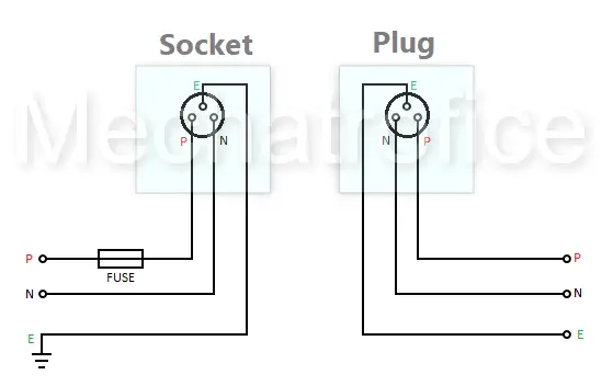
The wiring of a Plug and socket is identical to each other. Generally, the phase and the neutral line are connected in the right and left side of the socket respectively, and earth at the top; as per the front view of the socket (below image). So, the front view of the plug should be just a mirror view of the socket that is the phase at left and neutral at the right side. This is to get the phase line in wires assigned for phase lines in both plug and socket.
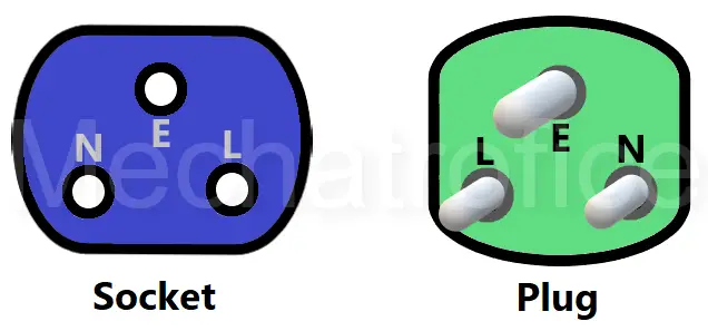
Even both lines are interchanged the device works fine as the AC supply has no fixed polarity. But the standard way and right practice are to match phase and neutral wires of both socket and plug.
Why it is? Suppose if you are connecting the plug of an extension box to the socket and the phase, neutral lines got interchanged, then the line connected through the switch in the extension box becomes the neutral line. So, whenever the switch of the extension board ON/OFF it just breaks the neutral line to the socket of the extension box but the phase line of the socket always remains charged. Any appliances connected through such an extension box will OFF and ON only due to an open or close neutral connection. The appliance will always have a hotline at its components even the switch is in the OFF position.
This is the same case even the device is connected directly to the socket, the ON/OFF switch of appliances controls only the neutral, the phase line always remains charged. So, try to avoid such issues during wiring.
Follow a standard color code during wiring, common wire colors used for Phase, Neutral and Ground lines are RED, BLACK, and Green respectively. Blue, yellow wires for phase, green-yellow wire for the earth, etc are also used for wiring.
The general method of choosing wire color code, insulations, method of electrical joints, etc various with countries or regions. Better to strictly follow the electrical standards and arrangements recommended in the respective regions. Because, during maintenance, fault detection, and repair works, it will be easy for the electricians to understand the wiring circuit and quickly identify the exact wires.
Refer:
How do Ups battery back up
You mean in wiring aspects or about the UPS device?
I need more lecture how to do electrical wiring in a new building
Nice
Electric board connection 4 switch 2 socket 1 indicator 1regulator