ON OFF Latching switch circuit diagram using IC 4017,555
A Push On Push off latching switch can use to ON and OFF the load alternatively with the same push action.
Push on push off switch using 4017
This circuit is using a decade counter IC 4017, which counts or shifts the output for each rising edge of applied clock signal. The IC has 10 outputs, here only two outputs are used to switch ON and OFF by shifting the HIGH state between these two outputs.
The output for ON/OFF is taken from output 1 at pin2. In the initial state output 0 is high and output 1 at pin 2 is in a low state. When we press the switch S1 the counter gets a positive edge triggering at the clock input pin 14. Now the High state shifts from output 0 to output 1 and Pin 2 will have a high state at the output.
When we press the switch again the HIGH state shifts to output 2 at pin4 and the output at pin 2 switches to a LOW state. Here the output 2 which is at pin4 is connected to the reset pin 15 of the IC. So when the output is shifted to pin4 it instantly resets the IC to the initial state with a HIGH state at pin3 and a LOW state at Pin 2. And this shifting repeats for each pulse, thus the circuit obtains an output at pin2 that can repeatedly ON and OFF with each switch press or positive pulse at the pin14.
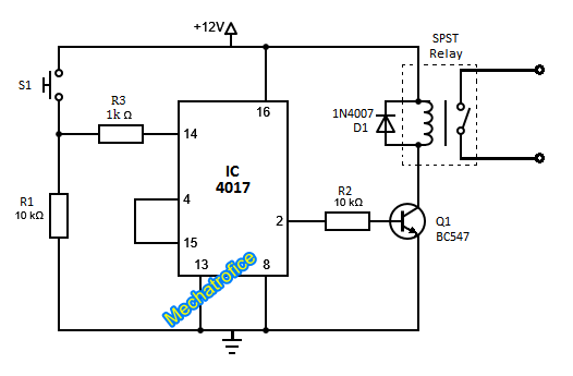
The output current of an IC 4017 has just a few milliamperes. So, in order to use the toggle circuit with high power loads, it needs to be driven with a transistor. In the circuit, the output is arranged to drive an SPST relay for ON & OFF the loads that need to be connected with an external supply.
Components required
IC – 4017
Resistor – R1,R2 – 10k, R3-1K
Transistor – Q1 – BC547
Diode – D1 – 1N4007
Switch – S1-push switch
Relay – SPST – 12V,200ohms
ON OFF LAtching switch using 555 IC
Here, the circuit is using IC 555 for the push on push off operation.
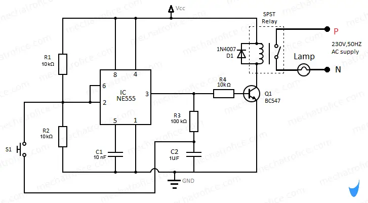
The output of the 555 IC switches to high when the voltage at trigger pin 2 is below vcc/3. Once it is triggered the output remains high even the voltage at pin 2 is above Vcc/3, it can be switched to LOW state only by applying a voltage above 2Vcc/3 at the threshold pin 6.
Refer: Working of 555 IC
Here the pin2 and 6 are connected together to a resistor voltage divider which gives a voltage of Vcc/2 at both the pins. When the switch S1 is open both pins will have this Vcc/2 voltage which is a value between the trigger and threshold values. At this voltage level the IC neither trigger nor switches to LOW state, it will remain in the same output state; in the initial condition, it remains in the LOW state.
The capacitor C2 is connected to the output pin through the resistor R3, C2 charges if the output is high, and remains discharged if it is low. Initially, the voltage across C2 will be almost equal to zero because the output is low.
The push switch S1 is connected between the capacitor C2 and the resistor R2. When we press the switch S1 the voltage across R2 instantly becomes equal to the voltage across the C2.
The voltage across C2 is low when the output state is LOW, so on pressing the switch the voltage across the R2 drops below Vcc/3 which triggers the IC, and the output switches to a high state. Now the Output is HIGH and on releasing the switch the C2 starts to charge through R3. It will charge to a voltage value equal to the output voltage which is above 2Vcc/3. The Output state remains high because on releasing the switch the voltage at pin2 & 6 becomes Vcc/2.
So next time when the switch has pressed the voltage across the R2 will be above 2Vcc/3 and the output switches to LOW state. Now the capacitor discharges through R3 and reaches the LOW state voltage value and remains in this state. This repeats in each consecutive switch press and the output can be alternately turned ON and OFF by pressing a single switch S1.
Using the relay circuit driven through the transistor Q1, the circuit can be used to operates AC loads or other devices. The relay can be replaced with a load if the load is to be operated with the same supply.
Components required
IC – 555
Resistor – R1,R2,R4 – 10k, R3-100K
Capacitor – C1 – 10nf, C2 – 1uf
Transistor – Q1 – BC547
Diode – D1 – 1N4007
Switch – S1-push switch
Relay – SPST – 12V,200ohms
Does it work
yes i tried this it’s worked
Is this circuit working? I try both circuit।but not working