Voltage controlled oscillator circuit – VCO using 555
A Voltage controlled oscillator (VCO) circuit varies its frequency of the oscillation with respect to the externally applied voltage. The VCO circuit can obtain a linear variation of oscillation in relation to the input voltage.
The VCO circuit shown here consists of a 555 astable multivibrator, which generates a square wave output with a duty cycle of 50 percentages.
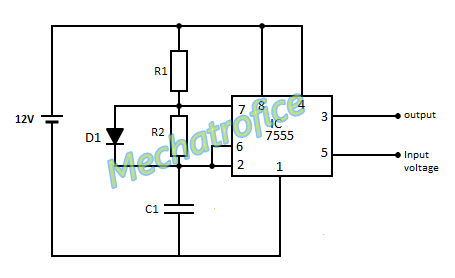
In the circuit, the external input voltage is applied to the control voltage pin 5 of the IC. The applied voltage can be varied from zero up to maximum value of supply voltage (here from 0 to 12V). Thus the output frequency of the multivibrator will proportionally vary with the voltage variation from 0 to 12V. For an open control voltage, the pin 5 has a voltage of 2/3 of the supply voltage. At this condition, the circuit generates a frequency around 154khz.
The value of threshold voltage and trigger voltage changes with the value of control voltage. Hence the charging time of the capacitor varies with the control voltage. So any increase or decrease in the control voltage increases or decreases the charging time of capacitor respectively. And thereby the time period of the output waveform. Hence the oscillation of the circuit can control by means of an external voltage.
Here the input voltage proportionally varies the time period of the output wave. As the frequency value is an inverse of the time period, the frequency varies linearly inverse to the input voltage.
components required
Integrated circuit – IC1 – 7555
Resistor – R1, R2 – 1kΩ
Capacitor – C1 – 10nf
Diode – D1 – 1N4007