L293D Motor Driver Module Arduino Tutorial – DC motor control
L293D Motor Driver
L293D is a 16 pin motor driver IC consist of quadruple half H drivers. It can simultaneously control the direction and speed of two DC motors. L293d is a suitable device to use for stepper motors, gear motors etc.
The IC has an operating voltage range from 4.5 V to 36 V. The L293 and L293D models can drive current up to 1A and 600mA respectively.
L293d pin diagram
L293D pinout 16 Pin PDIP Package
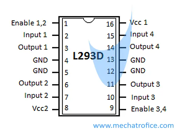
IC L293D pin functions
Pin 1: Enable 1,2 – This is an active high input. When the pin is high it enables the driver channels 1 and 2.
Input High state – Enabled.
Input Low state – Disabled.
Pin 2: Input 1 – Digital input to control the output 1. The state of all outputs OUT1, OUT2, OUT3, OUT4 will be same as the input state applied at the corresponding inputs.
Output = Input.
High input – High output.
Low input – Low output.
Pin 3: Output 1 – Connected to one of the terminals of the motor 1; motor 1 – connected across the output 1 and 2.
Pin 4: GND – Heatsink and Ground Connection. The GND connection itself used as the heat sink to disperse the heat.
Pin 5: GND – Heatsink and Ground Connection.
Pin 6: Output 2 – Connected to the remaining terminal of the motor 1. Motor terminals should be connected with respect to the inputs assigned.
Pin 7: Input 2 – Digital input to control the output 2.
Pin 8: Vcc2 – Supply to the motors, 4.5V to 36V. The supply must be connected to a source capable enough to drive the current requirement of the load.
Pin 9: Enable3,4 – It is also an active high input. It is to enable and disable the driver channels 3 and 4.
Pin 10: Input 3 – Digital input to control the output 3.
Pin 11: Output 3 – Connected to one of the terminals of the motor 2; motor 2 – connected across the output 3 and 4.
Pin 12: GND – Heatsink and Ground Connection.
Pin 13: GND – Heatsink and Ground Connection. The Ground terminals should be soldered to a metallic area in the PCB which is enough to transfer the heat generated.
Pin 14: Output 4 – Connected to the remaining terminal of the motor 1.
Pin 15: Input 4 – Input to control the output 4. All the inputs are permitted only up to a maximum of 7V.
Pin 16: Vcc1 – 5V supply for the functioning of the IC.
L293D working
The IC L293D works with an H bridge arrangement, which can alternate the polarity across a load or change the direction of the current.
Refer: DC motor direction control
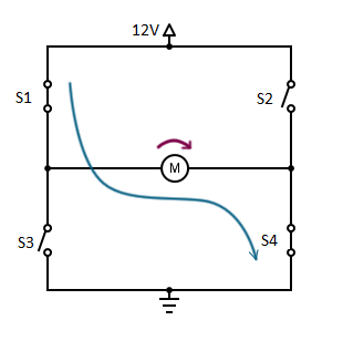
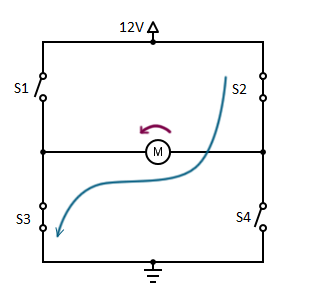
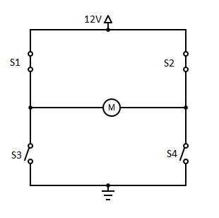
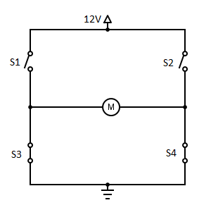
H bridge Truth table
| S1 | S2 | S3 | S4 | Motor Direction |
| 0 | 0 | 0 | 0 | Freerunning |
| 1 | 0 | 0 | 1 | Clockwise |
| 0 | 1 | 1 | 0 | Anticlockwise |
| 1 | 1 | 0 | 0 | Brake |
| 0 | 0 | 1 | 1 | Brake |
The s1 and s3, s2 and s4 are not permitted to close at a time as it will short circuit the supply.
Simply, what a motor driver does is it act as a current amplifier which gives high current outputs to drive the motor from a low current control signal. Driver IC or a driver circuit is a similar H bridge arrangement instead of switches replaced with transistors, MOSFETs, etc. Hence low current input signals can switch these devices and operate in the same way as an H bridge circuit works.
L293D Function Table
| INPUT | OUTPUT | Motor Direction | ||
| IN1/IN3 | IN2/IN4 | OUT1/OUT3 | OUT2/OUT4 | |
| 0 | 0 | 0 | 0 | Brake |
| 1 | 0 | 1 | 0 | Clockwise |
| 0 | 1 | 0 | 1 | Anti-clockwise |
| 1 | 1 | 1 | 1 | Brake |
L293D motor driver Arduino interfacing
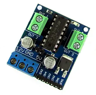
Driver IC L293D is available as module and Arduino shield. L293D Motor Driver modules usually come with an inbuilt Lm317 voltage regulator circuit or similar voltage regulating circuit, along with connectors.
There is no difference in program or connection vice while using the L293D IC directly or through a module.
Connect the 4 inputs and 2 enable pins to the respective digital output pins of the arduino as declared in the code.
Driver module
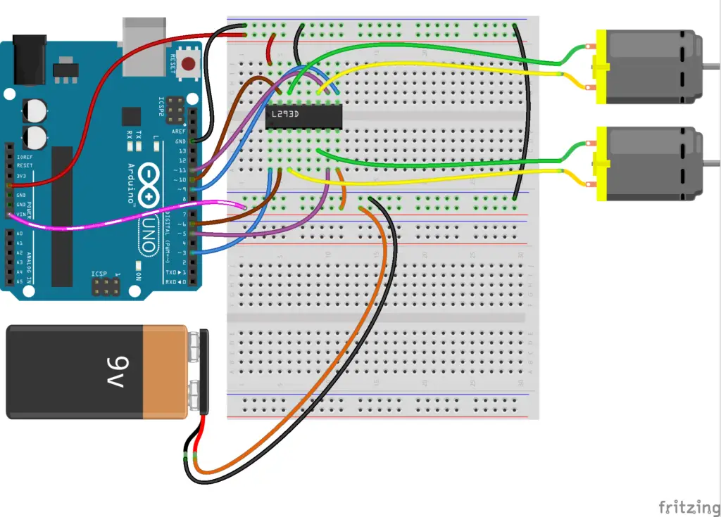
L293d motor driver module connection with Arduino Uno
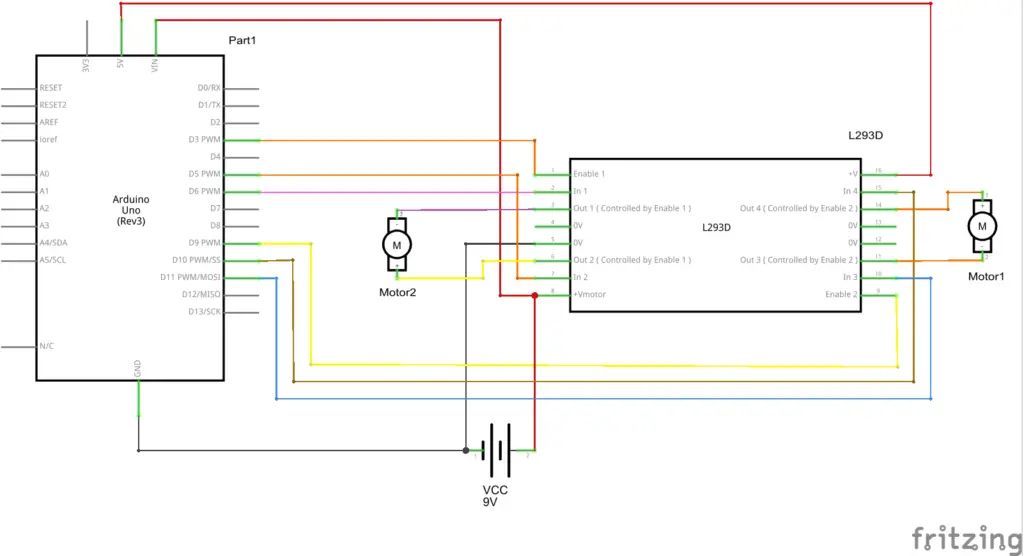
The below arduino code just show you how the motor direction changes with the change in respective input states. As given in the code, for five seconds the motor runs in the clockwise direction, then in the counterclockwise direction and then stops; this repeats again.
L293d motor driver Arduino code
const int IN1 = 6, IN2 = 5, IN3 = 11, IN4 = 10;
const int enable12 = 3 , enable34 = 9;
void setup()
{
  pinMode(IN1, OUTPUT);
  pinMode(IN2, OUTPUT);
  pinMode(IN3, OUTPUT);
  pinMode(IN4, OUTPUT);
  pinMode(enable12, OUTPUT);
  pinMode(enable34, OUTPUT);
  digitalWrite(enable12, HIGH);
  digitalWrite(enable34, HIGH);
}

void loop()
{
  clockwise();
  delay(5000);
  anticlockwise();
  delay(5000);
  brake();
  delay(5000);
}
// Input state to rotate 2 motors CW
void clockwise()
{
  digitalWrite(IN1, HIGH);
  digitalWrite(IN2, LOW);
  digitalWrite(IN3, HIGH);
  digitalWrite(IN4, LOW);
}
// Input state to rotate 2 motors CCW
void anticlockwise()
{
  digitalWrite(IN1, LOW);
  digitalWrite(IN2, HIGH);
  digitalWrite(IN3, LOW);
  digitalWrite(IN4, HIGH);
}
//Motor Brake
void brake()
{
  digitalWrite(IN1, LOW);
  digitalWrite(IN2, LOW);
  digitalWrite(IN3, LOW);
  digitalWrite(IN4, LOW);
}
Where can I obtain the particular motor driver module shown in this article?
It is available in e-commerce websites or you can find it from an electronics shop that sells hobby kits, electronics project kits, etc.
excellent article. Is it possible to connect a 24v motor which is used for boom gate control. If so how could give 24v power? Thank you
L293 supports 24V since it has a 4.5 to 36V operating range. But if the current required for the motor is high then you have to use relays or some other drivers with high load ratings.
Thank you very much for the reply. It is appreciated if you could give me a sketch and schematic diagram if a relay is used to control 24v motor. Thanks in advance.
Refer : http://mechatrofice.com/circuits/relay-dc-motor-driver ; motor direction control using relay.
& http://mechatrofice.com/arduino/relay-module-interface ; relay module arduino interfacing