Obstacle detection using IR sensor arduino
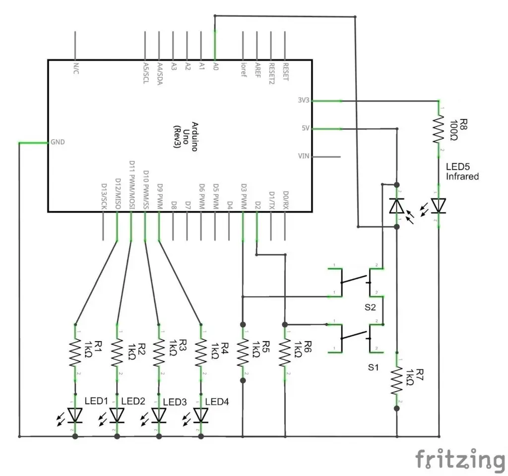
In this IR proximity sensor system, the distance from the sensor to the object is indicated by 4 LEDs. It is calculated in terms of the voltage obtained by the IR sensor at different object distances. And compare these values with 4 reference values. The reference values are the corresponding voltage values generated when the object is placed at particular distance points. That is 4 distance point represents 4 voltage values. The 4 LEDs will ON one by one, as the object cross each distance points.
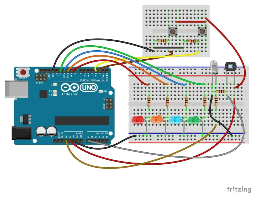
Here the analog input pin A0 is connected to the IR diode. The voltage at this pin varies proportionally with the rate of infrared reflection. At a closer distance, the A0 have higher values due to high reflection intensity.
In this system, after uploading the code. The minimum and maximum distance have to set manually. Because then only the system can divide this distance range to 4 reference values. The shortest distance variable “mindistance” is taken due to the requirement of minimum distance for the reflection of IR rays.
To set minimum distance, press the switch S1 and place an object close in front of the IR sensor. Then release the switch at a maximum value of the variable “mindistance”. That is at the threshold minimum distance. Closer beyond this point returns a low value due to zero reflection. Because the object completely covers the IR rays from IR LED. Active high state at pin2 sets the minimum distance value from the current analog voltage at the analog input A0.
Similarly, press the switch S2 and place the object as far as possible. Set the maximum distance by release S2 at the lowest value above zero. Because the value just above the zero is the maximum range that the IR can reach and detect.
The values of “mindistance”, “maxdistance”, “distance “and “irread” displays line by line on the serial monitor. Use serial monitor for measuring the maximum and minimum values.
  Serial.println(mindistance);
  Serial.println(maxdistance);
  Serial.println(distance);
  Serial.println(irread);
Then the difference of shortest and the maximum distance is divided into 4 distance units, which is indicated by corresponding LEDs.
We can set different minimum and maximum values than the actual minimum and maximum values of the system. It will vary the distance points and range of operation. Beyond that, the system will give a null response.
Code
int irread, distance, mindistance, maxdistance;
void setup() {
  pinMode(12, OUTPUT);
  pinMode(11, OUTPUT);
  pinMode(10, OUTPUT);
  pinMode(9, OUTPUT);
  tone(5, 38000);
  Serial.begin(9600);
}

void loop() {
  // To find minimum distance connect digital pin2 to high state.
  if (digitalRead(2) == HIGH) {
    mindistance = analogRead(A0);
  }
  // To find maximum distance connect digital pin3 to high state.
  if (digitalRead(3) == HIGH) {
    maxdistance = analogRead(A0);
  }
  // working range of proximity sensor
  distance = mindistance - maxdistance;
  irread = analogRead(A0);
  Serial.println(mindistance);
  Serial.println(maxdistance);
  Serial.println(distance);
  Serial.println(irread);
  if (irread >= (maxdistance) {
  digitalWrite(12, HIGH);
  }
  else {
    digitalWrite(12, LOW);
  }
  if (irread >= (distance / 3) + maxdistance) {
  digitalWrite(11, HIGH);
  }
  else {
    digitalWrite(11, LOW);
  }
  if (irread >= (distance * 2 / 3) + maxdistance) {
  digitalWrite(10, HIGH);
  }
  else {
    digitalWrite(10, LOW);
  }
  if (irread >= mindistance) {
  digitalWrite(9, HIGH);
  }
  else {
    digitalWrite(9, LOW);
  }
}