Simple touch switch circuit using transistor, 4017, 555 IC
A touch switch is a device that operates with the touch action of an object or sensible material. It is used in hobby circuits to high-end consumer electronics for various applications. Below are a few easy circuits to make a touch switch.
Touch switch circuit using transistor
The given touch switch circuit works with an arrangement of two NPN transistors similar to darlington pair, which can obtain a high current gain for the input base signal.
In the circuit, the emitter of transistor Q2 is connected to the base of the transistor Q1. So the emitter current of Q2 which is the sum of the input signal (base current Ib) and the amplified signal of Q2(collector current – βIb) is again amplified by the Q1. Thus the resultant output has extra sensitivity to the input signal.

The given circuit is a basic design to just operate a single LED with a 3V supply like a momentary switch. The circuit can be further modified for additional applications.
Components required
Transistor – Q1,Q2- BC547
Resistor – R1 – 1k, R2 – 220Ω
LED – Red
Supply – 3V battery
Piezo touch switch circuit using 4017 IC
In this touch switch, a piezoelectric sensor is used to sense the touch action. It can generate an electrical charge from any change in physical parameters such as pressure, strain, force, acceleration, and temperature.
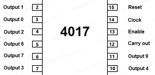
In the circuit, a decade counter IC 4017 is used to work as a latching switch for successive touch actions. The counter IC shifts its output for each positive edge applied to the clock input at pin 14. The first output of the counter is taken as output for this circuit which is at pin 2. Hence in the initial state, the output 0 is in a high state and the rest including the first output is in a low state.
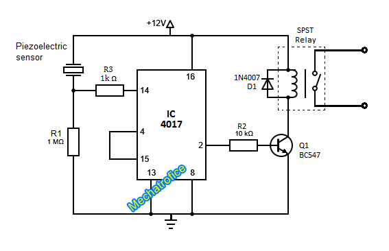
When the piezo is touched it causes a voltage to form across the R1 which gives a positive edge to the clock input. Now the High state shifts from output 0 to output 1 and Pin 2 will have a high state. Through Q1 the relay energizes and closes the contact to ON the connected device.
When again the piezo is touched the next positive edge shifts the output to output 2 which is at pin3. This pin 3 is connected to the reset pin 15 of the IC which instantly reset the IC to the initial state which OFF the circuit. This repeats on each touch action.
The sensitivity of the touch can be adjusted by varying the resistor connected across the pin 14.
Components required
IC – 4017
Piezoelectric sensor
Resistor R1 – 1M, R2 – 10k, R3-1K
Transistor – Q1 – BC547
Diode – D1 – 1N4007
Relay – SPST – 12V,200ohms
Supply – 12V
Simple Touch alarm circuit using 555 IC
Here the circuit diagram for a piezo-sensor-based touch alarm. Unlike from normal 555 touch plate switch, the piezoelectric touch switches are more sensitive and accurate in action.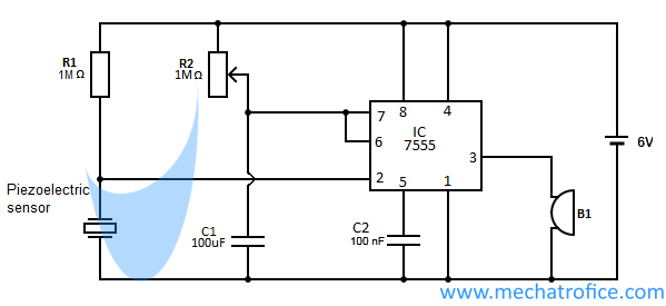
The circuit consists of 7555 IC, which is the CMOS version of the 555 IC.
When a voltage below 1/3 of the supply voltage is applied to the triggers pin 2, the output switches to a high state and ON the buzzer. Here on touching the piezoelectric sensor the vibration or pressure generates a proportional voltage change forms across it. Here when the voltage across pin 2 drops below vcc/3 the IC triggers.
Once the circuit is triggered, the output will remain ON until the voltage at pin 6 reaches 2/3 of the supply voltage. This circuit is a one-shot or 555 monostable multivibrator circuit, which uses an RC circuit by connecting the threshold pin across the capacitor. The duration of ON time is the time required for the voltage across the capacitor to reach the threshold voltage. The ON time can be adjusted by varying the 1M potentiometer. It can be calculated as,
Time period = 1.1 R C.
Here in this circuit by adjusting the potentiometer a maximum ON time of 110 seconds can be obtained.
Components required
IC1 – 7555
Piezoelectric sensor
Resistor – R1 – 1M, R2 – 1M pot
Capacitor – C1 – 100uf, C2 – 100nf
Buzzer
Battery-6V

I haven’t yet wired up your 555 circuit, but it looks like what I am looking for.
I have designed a digital foot drum using a PIC. It is triggered by a footswitch connected to a digital input pin on the PIC.
This is not a very good solution and want to replace the footswitch with a piezo triggered circuit.
What modifications to your circuit do you think I need to make this work?
Regards
Pete
That is, you are trying to give digital input to the PIC from a piezo output.
If you are using the above 555 circuit, you can connect the output pin 3 to the digital input through an optocoupler isolation circuit or A/D protection circuit.
But for a piezo trigger circuit, why don’t you use the analog input of the microcontroller. With analog read, you can set various threshold values to trigger with required vibration levels. Refer Vibration sensor alarm project arduino.
I am planning to run your 555 circuit on a 3V battery, would it work? I am planning to use a Panasonic 3v battery to power the circuit, do you think I will be able to achieve 2 years of it. I will running this circuit to trigger a wireless security alarm.
The operating voltage of a 555 ic is 4.5 – 16V range. But an IC 7555 (CMOS version of 555 IC) has a guaranteed supply voltage range of 2V to 18V. So try an experiment with a 7555 IC.
Thanks. It works. How can I increase the sensitivity of the crystal. It needs quite a touch to trigger. I would like to to be triggered on slightest knock or vibration.
The sensitivity of the circuit is limited. The only thing you can do is increase the Resistance R1 (still limited) or find a high sensitive piezo sensor.
Do you have any recommendations to use some other configuration?
Try connecting the piezo through an NPN transistor.

If you want to sense minute vibrations, I recommend going for a microcontroller circuit. Arduino piezo vibration sensor