Arduino Relay Module Connection Tutorial
Relay modules are assembled units commonly included with Optocouplers, diodes, LEDs, transistors, etc.

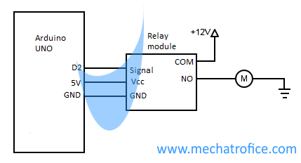
An input section of the relay module consists of three terminals VCC, GND, and a signal input (IN1). The output contacts of the module have three connections, labeled as Common (COM), Normal close (NC), and Normal open (NO). If the load connection is through the COM and NC, the terminals will be closed for a LOW state input signal and open during HIGH state input. Just opposite to that if the connection is through COM and NO then the HIGH state-input closes and the LOW state opens the connection.
Arduino relay module pinout
| Arduino | Relay Module |
| +5V | Vcc |
| GND | GND |
| Digital Pin 2 | Signal input (IN) |
The pin arrangements of the relay modules may be different from one another. The chance of damage to the module due to the wrong connection is considerable, so check the label of each pin and ensure the contacts are correct.
Multi-channel Relays can be interfaced in the same way only additional input pins IN1, IN2, IN3,etc., need to be connected to the module from the Arduino outputs.
For 12V or high power relays external DC supply is required. While using external supply common ground terminals should be connected to the module and the Arduino.
Code
const int signail_in = 2;
void setup() {
  // initialize digital pin signail_in as an output.
  pinMode(signail_in, OUTPUT);
}

void loop() {
  // turn the Motor on  by making the signal input HIGH
  digitalWrite(signail_in, HIGH);
  // wait for 3 second
  delay(3000);
  // turn the motor off by making the signal input LOW
  digitalWrite(signail_in, LOW);
  // wait for 5 second
  delay(5000);
}
In the above code, the output of the digital pin 2 repeatedly switches HIGH and LOW for a period of 3 seconds and 5 seconds respectively. Hence the relay output switches the motor ON for 3 seconds and OFF for 5 seconds, and this will continues infinitely.

can i want the schematic diagram for this circuit?
It has been added to the post as per your request.
What should be connected to the SIGNAL pin?(or how this connection should be made to complete?
You can use any digital output pin of the Arduino to connect the signal input.
Refer for circuits and codes using relay: http://mechatrofice.com/arduino/relay-timer-switch
Please what if i want the output to be off when it reaches some degree and also on at some specific degy.
Since you have no any feedbacks in this circuit and as it is just switching ON and OFF the motor supply you can’t control the position.
But you can control the ON time and OFF if the motor rotation with respect to time is definite.
For degree-based movement, you have to use a servo motor or stepper motor. Or own feedback mechanism to get the shaft position of the motor, like using a potentiometer, etc.