Logic Gates viva interview Questions and Answers
• What is a logic gate?
A logic gate is a basic building block of a digital circuit that has two inputs and one output. The output of a logic gate is determined based on certain logic rules, depending on the type of the gate.
• What is a truth table?
A truth table is a mathematical table used in logic to compute the functional values of logical expressions on each of their functional arguments, that is, for each combination of values taken by their logical variables.
• What is a binary system?
A binary system is a number system that uses two distinct symbols, typically 0 and 1, to represent numbers. It is the foundation of all digital computing systems.
• What is Boolean algebra?
Boolean algebra is a branch of algebra where the values of the variables are the truth values true and false, usually denoted 1 and 0, respectively. It is used in the design and analysis of digital circuits.
• Explain basic types of logic gates?
The basic types of logic gates are AND, OR, NOT, NAND, NOR, XOR, and XNOR.
- A Buffer Gate is Logic Gate that has only one Input, its Output follows the same Logic State as the Input.
A Output 0 0 1 1
- NOT Gate: A NOT gate, also known as an inverter, operates by outputting the inverse of its input. If the input is true or ‘1’, the output is false or ‘0’, and vice versa.
A Output 0 1 1 0
- AND Gate: An AND gate performs a logical conjunction on its inputs. This gate operates by giving a high output (1) only when all its inputs are high. If any input is low (0), the output will also be low.
A B Output 0 0 0 0 1 0 1 0 0 1 1 1 
- OR Gate: This gate functions by accepting two electrical inputs. If either input is switched on (carries a number 1), the output will also be 1. If both inputs are off (0), the output will be 0.
A B Output 0 0 0 0 1 1 1 0 1 1 1 1
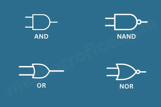
- NAND Gate: This gate, also known as the “not AND gate”, provides a low output (0) only when all its inputs are true. In all other cases, the output is high (1). It’s essentially the inverse of an AND gate.
A B Output 0 0 1 0 1 1 1 0 1 1 1 0 - NOR Gate: Also known as the “not OR gate”, this gate gives a high output (1) only when all its inputs are false. If any input is true, the output is low (0). It’s the inverse of an OR gate.
A B Output 0 0 1 0 1 0 1 0 0 1 1 0 - XOR Gate: The XOR gate, or Exclusive OR gate, is a digital logic gate that provides a true (1 or HIGH) output when the number of true inputs is odd. It implements an exclusive OR, meaning a true output results if one, and only one, of the inputs to the gate is true.
Input A Input B Output (A XOR B) 0 0 0 0 1 1 1 0 1 1 1 0
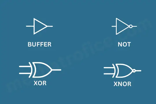
- XNOR Gate: The XNOR gate, or Exclusive NOR gate, is a digital logic gate whose function is the logical complement of the Exclusive OR (XOR) gate. A high output (1) results if both of the inputs to the gate are the same. If the inputs are different, a low output (0) results.
Input A Input B Output (A XNOR B) 0 0 1 0 1 0 1 0 0 1 1 1
• Explain the concept of Universal Gates?
Universal gates are types of gates that can be used to implement any kind of logic function. NAND and NOR gates are known as universal gates.
• Why are NAND and NOR gates called universal gates?
NAND and NOR gates are called universal gates because they can be used to construct all other types of logic gates.
• Where are XOR gates used?
XOR gates are commonly used in applications like binary addition, subtraction, parity checking and parity generation.
• Explain the difference between a latch and a flip-flop?
Both latches and flip-flops are circuit elements that are used to store and manipulate binary information. The key difference between them is that a latch is level-triggered (the output can change as long as the input is active), while a flip-flop is edge-triggered (the output can only change at specific times, typically when a control signal goes from high to low or low to high).
• What is a multiplexer?
A multiplexer, or mux, is a combinational circuit that selects binary information from one of many input lines and directs it to a single output line. The selection of a particular input line is controlled by a set of selection lines.
• Explain the working of a demultiplexer?
A demultiplexer, or demux, is the reverse of a multiplexer. It takes a single input and routes it to one of several outputs. The output line that is chosen for the input is determined by a set of selection lines.
• What is a half adder?
A half adder is a type of digital circuit that performs the addition of two binary numbers. It produces a sum and a carry value which are both binary digits.
• What is a full adder?
A full adder is a digital circuit that performs addition of three binary numbers. The three inputs are A, B, and C_in (carry input). The two outputs are S (sum) and C_out (carry output).
• What is a decoder?
A decoder is a combinational circuit that converts binary information from n input lines to a maximum of 2^n unique output lines.
• What is an encoder?
An encoder is a combinational circuit that converts information from 2^n inputs to n outputs, essentially performing the reverse operation of a decoder.
• What is a shift register?
A shift register is a type of sequential circuit that is used to store and transfer data. It consists of flip-flops connected in a chain so that the output from one flip-flop becomes the input of the next.
• What is a binary counter?
A binary counter is a type of digital circuit that goes through a predetermined sequence of binary values. The output of a binary counter can be used to count the number of pulses in a digital signal.