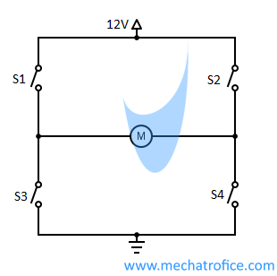
DC motor direction control using relay circuit
A Relay based DC motor controller works with an H-bridge arrangement. With an H-bridge circuit, the polarity across a load can be altered in both directions.
In the Dual SPDT motor driver circuit, the DC motor terminals are connected between the common poles of the two relays. The normally closed terminal of both relays is connected to negative or ground. And the normally open terminals are connected to the positive terminal.
The coil terminals of the relay are connected to the supply with a push switch. The Switch S1 and S2 control relay 1 and relay 2 respectively.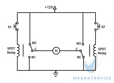
In the circuit diagram shown, switch S1 is ON, and switch S2 is OFF. So, the motor terminals will have a positive polarity on the left side and a negative polarity on the right side. Thus, the motor turns in a clockwise direction. Similarly, when the S2 is ON and S1 is OFF, the motor turns in an anticlockwise direction.
Motor modes of operation
| S1 | S2 | Motor Movement |
|---|---|---|
| 0 | 0 | Motor brakes |
| 1 | 0 | Motor moves right |
| 0 | 1 | Motor moves left |
| 1 | 1 | Motor brakes |
When two switches are open, both the relays are will be in a normally closed position. Which makes the ground or negative across the motor terminals, that is the same polarity on both sides. Similarly, when both switches are closed (here both terminals will have positive voltage) the same polarity will obtain at two sides. On both conditions, the motor terminals are shorted, and the motor brakes.
In a relay H-bridge, the motor terminals have no free-floating terminal states. So a coast mode will not occur at any instant.
DC motor reversing circuit using DPDT relay
The direction of a DC motor can be controlled with the input polarity at the motor terminals. So here we are using a simple DPDT relay arrangement for polarity alternation.
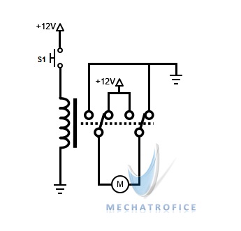
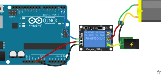
The diagram using a relay to reverse the motor will not energise the motor in any direction. The diagram is wrongly connected
That wasn’t his goal, the goal was a direction changing circuit for a dc motor.
Hello Guys,
I have an actuator with a DC motor 24V. It has two wires for power Input terminal (no Feedback). Also between the power Input terminal and the motor there is a small board with two micro switches and 6 Diodes (S3GB) and one Coil (100) plus a unknown small SMD component between motor connection terminals . When applying 24 Vdc to input terminal motor does not work, voltage drops from 24 down to 1.7 V @ 6.5 Amps. But, driving the motor directly on a 24 Vdc runs the actuator normally (By-pass the electronic board that control the motor) with 3 A current consumption, so Mechanically the actuator is working. All diodes on the Board are okay, but the SMD component between motor terminal is shorted when measured with motor not connected. I have Board Image with components available if any one is interested to assist and help to identify the root cause.
Thanks in advance for post and the replay.