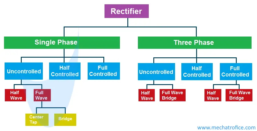
Different Types of Rectifiers – Single & Three Phase
A rectifier is an electronic circuit which converts Alternating Current into Direct Current. Based on the type of input supply, rectification and output it can be classified into different types.
Single Phase Rectifier
Single phase rectifiers are used to convert AC single phase supplies to DC. That is a single phase transformer is used to provide input to the rectifier. Single phase rectifiers are mainly used for low power application like a household appliance, consumer electronic devices, etc.
1φ half-wave rectifier circuit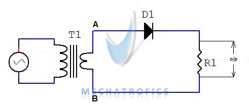
Three Phase Rectifier
A 3Φ Rectifier is an electronic circuit that converts three-phase AC supply into unidirectional DC output. 3 phase rectifiers are mainly used in industrial and high power applications.
In a three-phase electric power, an alternating current of the same frequency and voltage amplitude are carried through three conductors with a phase difference of 120 o degrees between each phase. Whereas a single phase supply is one of the three phases with respect to a neutral or common reference point of the 3 phase lines.
In three phase rectification, the output is obtained from the three phases fed into the rectifier circuit.

By Krishnavedala – Own work, CC BY-SA 3.0, Link
Single phase & Three phase rectifier comparison
| Single Phase Rectifier | Three Phase Rectifier |
|
|
Uncontrolled
An uncontrolled rectifier circuit is the general purpose rectifier circuits using diodes only. The diode rectifiers have no control over the output voltage hence called uncontrolled rectifiers.
Half Wave
A half wave rectifier is a type of rectifier which converts only positive half cycle of the input AC into pulsating DC.
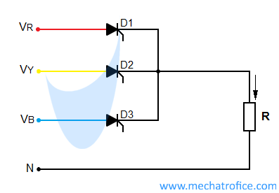
An uncontrolled 3 Phase half-wave rectifier circuit
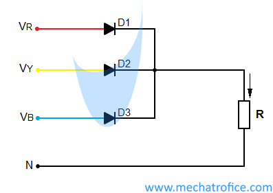
Here in the circuit 3 phase are connected to the anode of three diodes D1, D2, and D3. The cathode of all three diodes is connected to the one terminal of the load. The other terminal of the load is connected to the neutral. Hence, the maximum output voltage across the load is the maximum peak voltage of the phase line with respect to the neutral point which is ideally zero volts.
The diodes D1, D2, D3 alternatively conducts in respective to the phase change. The instantaneous output voltage will be equal to the voltage of the phase line which has the highest potential.
Full Wave
A Full Wave Rectifier is a rectifier circuit which converts both half cycles of the AC input into a pulsating DC.
Uncontrolled single phase full wave center tap rectifier circuit
The below 3 phase bridge rectifier circuit consists of six diodes. In a full wave rectifier, the voltage across the load is the voltage between two phases.
3φ Uncontrolled full wave bridge rectifier circuit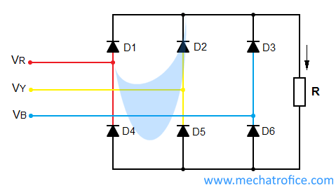
The diodes D1, D2, D3 selects when the respective phase comes the highest positive voltage and the diodes D4, D5, D6, select for the most negative voltage.
Half Controlled
Controlled rectifiers are a type of Phase controlled rectifiers which has control over the output using thyristors or SCRs. In this type of rectifiers, the output voltage of the rectifier can be regulated by controlling the triggering of the thyristor.
A thyristor or SCR is a multi-layer semiconductor device consists of three terminals anode, cathode, and gate. It functions as an electrically controlled switching device. It conducts only in one direction and always blocks the reverse current.
During reverse bias, a thyristor blocks the reverse current in the same way as a reverse biased diode works. But during the forward bias, it does not conduct as like a normal diode. In order to switch ON or trigger the SCR into conduction, a small amount of current is needed to be applied at its gate terminal. And on triggering the current starts to flows from Anode to Cathode.
The gate pulse is required just for triggering the device, once the SCR is triggered it remains in the conducting state regardless of the gate current after that. The SCR turns OFF when the forward current drops below its threshold value or by a negative gate current. In the rectifier circuit, the SCR turns off as the voltage reverses in the next half cycle.
Half Controlled 3 phase full wave bridge rectifier circuit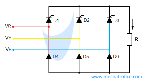
A half controlled rectifier consists of an equal number of thyristors and diodes, that is the total number of rectifier components are included of half number of SCR and half number of diodes. It means, a single phase half controlled bridge rectifier is made of 2 diodes and 2 SCRs; that is simply 2 diodes in an uncontrolled rectifier is replaced by two thyristors.
Full Controlled
In a Full Controlled Rectifier, all the components in the rectifier are switching devices which are controlled by an external pulse.
A full Controlled single phase full wave bridge rectifier circuit
The output regulation in a controlled rectifier is done by adjusting the firing angle or the time delay of the triggering pulse. By controlling the gate pulse the SCR can be switched ON at different angles of the phase and thereby phase of each half cycles can be controlled.
Full Controlled 3 phase half wave rectifier circuit