IC 4017 Decade counter Basics with Pinout
IC 4017 is a CMOS decade counter IC consists of a 5 stage Johnson counter with 10 decoded outputs that can count up to 10 decimals. It can be used for a variety of counter circuits and practical applications, like an LED chaser light circuit to even a non-contact AC detector circuit.
IC 4017 is a 16 pin IC. Out of 16, 10 pins are Output pins from output 0 to 9 that are pins 3, 2, 4, 7, 10, 1, 5, 6, 9, 11 respectively.
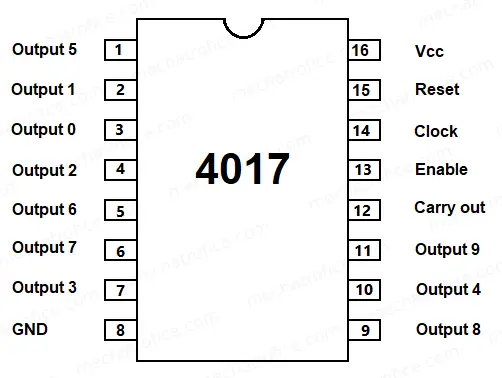
Pin 8: GND Pin
Pin 12: Carry out – A carry out completes its one cycle on every 10 clock input cycles. It is mainly used if the counter needs to be cascaded with any succeeding counter so as to count every 10 counts completed by the first counter.
Pin 13: Enable – It is an active low enable pin. It is usually connected to a logic low voltage which enables the counting. When applied with a high state it inhibits the clock input and stops the counting.
Pin 14: Clock input -The IC counts each rising edge applied to this input by 1.
Pin 15: Reset – It is an active-high reset. It is normally connected to GND or low voltage. If applied with a high state voltage it resets the counter and set to zero.
Pin 16: Vcc – The Vcc pin can be connected to a supply voltage ranges from 3V to 15V.
The 4017 IC counts for each positive or rising edge input given at the clock input. The output starts from output 0 and shifts the output towards output 9, once reached output count at 9 it repeats again from 0 and continues this rotation like a ring counter. On every count between 0 to 9, the respective output pin will have a high state and the rest of the outputs remains low; only one output will be high at a time.
Refer: LED chaser circuit using IC 4017; this exactly shows how its output works with a continuous clock pulse.
For example, if the count is currently 3 then the output 3 at pin7 is in a high state and all other pins are in a low state. If a square wave of 2 cycles is applied to the clock input, the output shifts to output 4 (pin 10) on the positive edge of the first cycle which changes output 3 to low state and output 4 to high state. Now the state maintains until the next positive edge of the second cycle arrives, then the output shifts to output 5 (pin1) and remains this state.
 The world of hobby 3D printing: Can non-techies make it?
 Solving any problems: Apply this simple technique
 How to overcome Laziness: The Japanese Kaizen 1 minute method
 5 simple Tips to fall asleep early at night