Servo Motor Control using Arduino Tutorial and Code
A servo motor is a rotary actuator mostly coupled with a shaft or arm. It has a position control associated with the servo mechanism. It uses a closed-loop control system with error-sensing negative feedback to correct the performance of a mechanism. A servo motor maintains accurate control of angular position and speed of motion of the rotor. The Servos have integrated drive gears and circuit, which precisely control the servo position.
The angular positions of a servo motor are controlled by the pulse width modulation(PWM).
The input pulse train at the control signal will turn the rotor to the desired position. The servo motor expects a control pulse at every 20 milliseconds (ms). The width of each pulse directs the servo to turn the shaft to the corresponding angular positions. That is the duration of the positive pulse in a 20ms total pulse width determines the servo shaft position. For a standard servo, 1ms positive pulse maintains a 0° and a maximum of the 2ms positive pulse will have a position of 180°.
Thus the pulse width between 1ms and 2ms obtains a corresponding position between 0° to 180° angles respectively.
How to Connect a Servo motor to Arduino
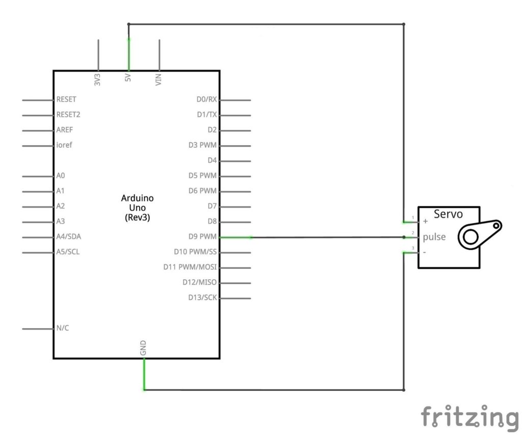
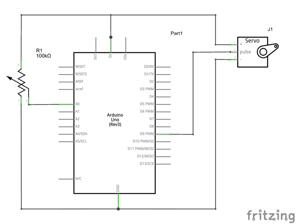
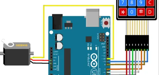
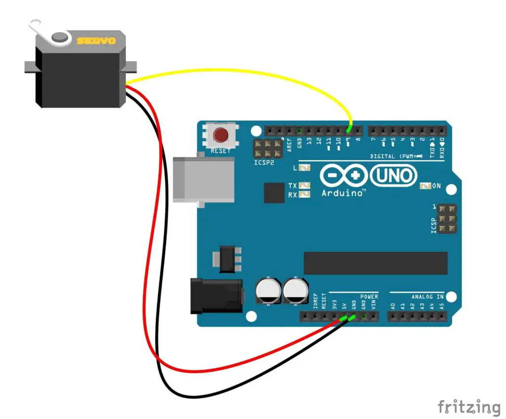 The servo motors are interfaced with the Arduino through a standard three-wire connection.
Servo motor interfacing with Arduino
Power
The power wire mostly has a red colour, which connects to the 5V pin of the Arduino.
The Servo motor requires a considerable amount of power, especially for high power servos. So, for multiple servos or while using servos along with other pins, it is better to power the servo motor separately with an external supply. Because the power at the remaining pins would be interrupted during its operation.
For external powering, connect the ground of the arduino commonly with the -ve terminal of the external power supply. And connect the supply terminal of the servo (+V) to the +Ve terminal of the external supply.
Ground
The ground wire typically has black or brown colour. It connects to the ground pin of the Arduino.
Control signal
The signal wire commonly has an orange colour. Yellow, white, blue colours are also used for this connection. One of the Digital pins of Arduino can be used for the signal connection. But, it is commonly used on PWM pins (3, 5, 6, 9, 10, or 11). The servo is mostly connected to pin 9 on the Arduino board. Even the servo is not in use, the analogWrite () (PWM) functionality on pins 9 and 10 disables by the accessing of the library function (except the Arduino Mega). Thus the remaining PWM pins can use for analogwrite () (PWM) by connecting servos to the pin 9 or 10.
Arduino Include Servo Library
The Arduino Platform itself has the code library for the servo motors. At the beginning of the sketch, the library function needs to be included as, #include <Servo.h>
Servo servo; create servo object to control a servo.
myservo.attach(9); attaches the servo on pin 9 to the servo object.
myservo.write(position); tell servo to go to position in variable ‘position’.
Arduino Servo Motor Sweep Code
A servo sweep circuit moves the servo shaft in to and fro motion. Which rotates the arm 180 degrees clockwise and 180 degrees anti-clockwise repeatedly.
Code
#include <Servo.h>

Servo myservo;
int pos = 0;

void setup()
{
  myservo.attach(9);
}

void loop()
{
  for(pos = 0; pos <= 180; pos += 1)
  {
    myservo.write(pos);
    delay(15);
  }
  for(pos = 180; pos>=0; pos-=1)
  {
    myservo.write(pos);
    delay(15);
  }
}
Arduino servo motor control with potentiometer
Servo motor position control arduino
Here we are controlling the angular position of a servo motor using a potentiometer. At every instant, the servo arm follows the position of the Knob. The servo moves clockwise or counterclockwise (0° – 180°) with the corresponding angular position of the potentiometer.
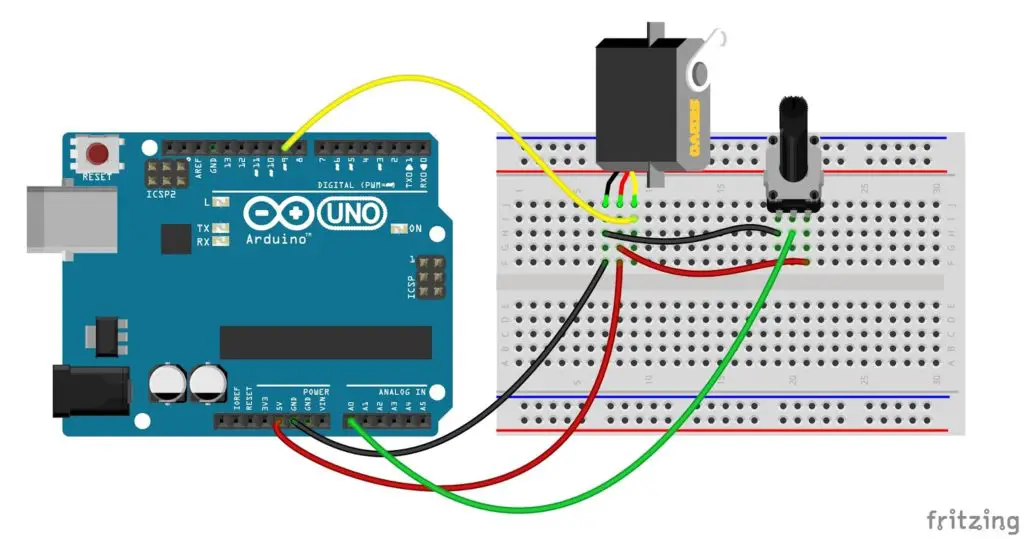 The wiper pin of the potentiometer is connected to analog input of the arduino. The terminal(T1) of the potentiometer is connected to supply voltage and the other terminal(T2) to the ground.
By turning the potentiometer, the input voltage varies in the range of 0 to 5V. The arduino uno has a 10-bit analog to digital converter. So the analog input values for the range 0 to 5 volt is converted into corresponding decimal values from 0 to 1023.
 In the program, we map the values between 0 – 1023 to 0° – 180°. Thus the angle of servo proportionally increments and decrements with the increase and decrease in input value. That is when the knob is at centre position the servo arm will be at 90°. And will turn towards 0° and 180° when rotating the knob towards GND terminal T2 and 5V terminal T1 respectively. Thus, every position change in the potentiometer will make the corresponding angular position change in the servo motor.
Code
#include <Servo.h>

Servo servo1;
int potin;

void setup()
{
  servo1.attach(9);
}

void loop()
{
  potin = analogRead(A0);
  potin = map(potin, 0, 1023, 0, 180);
  servo1.write(potin);
  delay(15);
}
Servo motor with LCD Angle Display
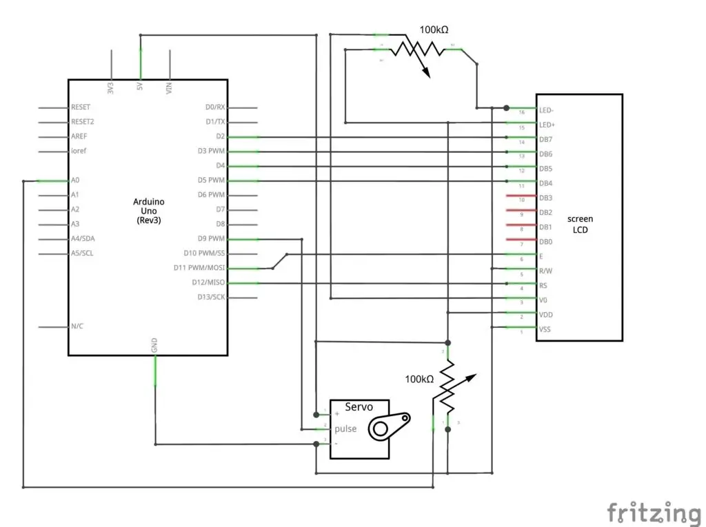
In this arrangement, the angles of the servo can be controlled by turning a knob and the current position of the servo will be displayed on the LCD. The servo motor follows the position change in the knob and so we can rotate the servo in clockwise or counterclockwise by rotating the wiper of the potentiometer. The LCD interfaced with Arduino display each present servo position from 0° to 180°.
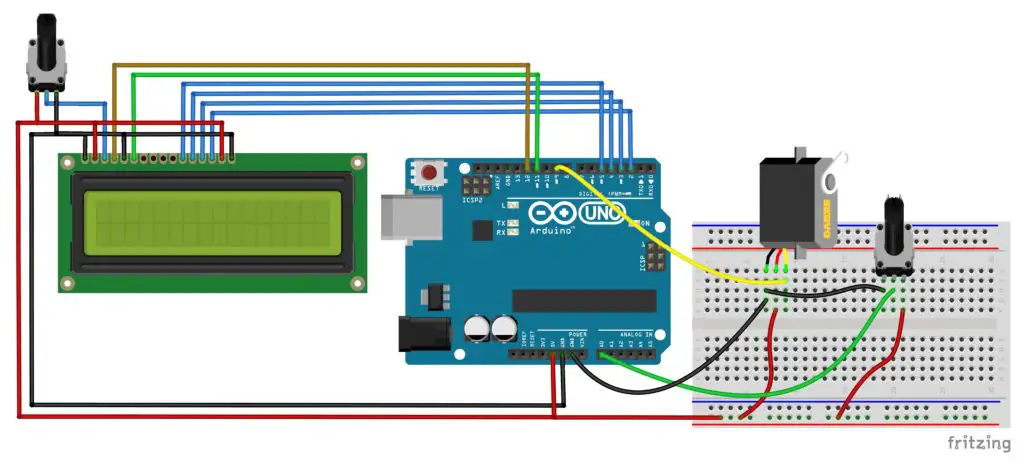 The circuit works as same as an in the servo knob, the only addition is an LCD interface to read out the position of the servo.
Code
#include <Servo.h>
#include <LiquidCrystal.h>

Servo servo1;
LiquidCrystal lcd(12, 11, 5, 4, 3, 2);
int potin;

void setup()
{
  servo1.attach(9);
  lcd.begin(16, 2);
  lcd.print("position=");
}

void loop()
{
  potin = analogRead(A0);
  potin = map(potin, 0, 1023, 0, 180);
  servo1.write(potin);
  delay(15);
  lcd.setCursor(9, 0);
  lcd.print(potin);
  lcd.print("degree");
}
Servo sweep with Knob speed control
The speed of the servo motor can be adjusted by the knob connected to the analog read pin 0 of the Arduino.
Code
#include <Servo.h>

Servo servo1;
int potin,pos;

void setup()
{
  servo1.attach(9);
}

void loop()
{
  for(pos = 0; pos <= 180; pos += 1)
  {
  potin = analogRead(A0);
  potin = map(potin, 0, 1023, 0, 1000);
  servo1.write(pos);
  delay(potin); // dealy of 0 to 1000ms
  }
  for(pos = 180; pos>=0; pos-=1)
  {
  potin = analogRead(A0);
  potin = map(potin, 0, 1023, 0, 1000);
  servo1.write(pos);
  delay(potin);
  }
}
Arduino control servo motor from the serial monitor
This servo motor drive system is a USB based servo controller. That is the servo motor can be controlled by a computer using Arduino serial communication.
Servo motor position control using serial monitor
To control the servo position the angles are entered as decimal input values in the range 0° to 180° in the serial monitor of the Arduino IDE.
Code 1
#include <Servo.h>

Servo servo1;
long num;

void setup()
{
 servo1.attach(9);
Serial.begin(9600);
Serial.print("Enter Position = ");
}

void loop()
{
  while(Serial.available()>0)
  {
  num= Serial.parseInt();
  Serial.print(num);
  Serial.println(" degree");
  Serial.print("Enter Position = ");
  }
  servo1.write(num);
  delay(15);
}
The code below, to control two servos through the serial monitor.
code 2
// Code for multiple servo attachment
#include <Servo.h>
Servo servo1;
Servo servo2;
long num1,num2;

void setup()
{
 servo1.attach(9);
 servo2.attach(10);
Serial.begin(9600);
// Separate the values of two positions with a comma.
Serial.println("Enter Position = servo1 degree, servo2 degree ");
Serial.print("Enter Position = ");
}

void loop()
{
  while(Serial.available()>0)
  {
  num1= Serial.parseInt();
  Serial.print(num1);
  Serial.print(" degree , ");
  num2= Serial.parseInt();
  Serial.print(num2);
  Serial.println(" degree ");
  Serial.print("Enter Position = ");
  }
  servo1.write(num1);
  servo2.write(num2);
  delay(15);
}
Serial monitor speed control of a sweeping servo
Here the speed of the servo can be adjusted by the serial input. The time delay is entered as decimal values in milliseconds.
Code
#include <Servo.h>

Servo servo1;
int num=5,pos;

void setup()
{
  servo1.attach(9);
  Serial.begin(9600);
  Serial.print("Enter delay time = ");
}

void loop()
{
  for(pos = 0; pos <= 180; pos++)
  {
  while(Serial.available()>0){
  num= Serial.parseInt();
  Serial.print(num);
  Serial.println(" ms");
  Serial.print("Enter delay time = ");
  }
  servo1.write(pos);
  delay(num);
  }
  for(pos = 180; pos>=0; pos--)
  {
  while(Serial.available()>0){
  num= Serial.parseInt();
  Serial.print(num);
  Serial.println(" ms");
  Serial.print("Enter delay time = ");
  }
  servo1.write(pos);
  delay(num);
  }
}
Position and speed control of servo motor using Arduino serial monitor
This Arduino sketch is to control the position and speed of a servo motor using Arduino serial communication. Here the input decimal values of position and the speed of the shaft movement can be given through the serial monitor. The values can be separated by entering the position and the time delay by a comma.
Code
#include <Servo.h>

Servo servo1;
long num, delays;
int i=0;
void setup()
{
 servo1.attach(9);
Serial.begin(9600);
Serial.println("Enter Position and delay = position , delay ");
// Separate the values of position and delay by a comma.
Serial.print("Enter Position and delay = ");
}

void loop()
{
  while(Serial.available()>0)
  {
  num= Serial.parseInt();
  Serial.print(num);
  Serial.print(" degree , ");
  delays = Serial.parseInt();
  Serial.print(delays);
  Serial.println(" ms");
  Serial.print("Enter Position and delay = ");
  }

  while (i<num){
  i++;
  servo1.write(i);
  delay(delays);
}
 while (i>num){
  i--;
  servo1.write(i);
  delay(delays);
}
i = num;
}
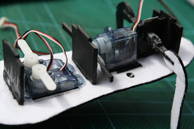
Continuous servo motor
A continuous servo motor or 360° servo has a shaft that rotates continuously. Unlike a standard servo it has no position control but the speed and direction of rotation can be controlled.
The connection of a continuous is same as a standard servo motor, it also has three wires Vcc, GND and signal.
FEETECH FS5106R, Parallax Feedback 360°, SpringRC SM-S4303R are models of continuous servo motors.
Continuous servo motor control
Continuous servo motors are controlled by the pulse width signals between 1000us and 2000us.
For a pulse width of 1000microseconds motor rotates clockwise at maximum speed. When the value increases from 1000us to 1500us the clockwise speed decreases and the motor stops at 1500 microseconds. Further increasing from 1500us the motor speed increases in counterclockwise direction till reaches the maximum speed at 2000us.
Continuous servo motor Arduino code
 #include <Servo.h>

Servo servo;

void setup()
{
  servo.attach(9);
}

void loop()
{
// rotates clockwise at full speed for 3 seconds.
  servo.writeMicroseconds(1000);
  delay(3000);
// rotates clockwise at half speed for 3 seconds.
  servo.writeMicroseconds(1250);
  delay(3000);
// rotation stops for 3s.
  servo.writeMicroseconds(1500);
  delay(3000);
// rotates counter counter clockwise at half speed for 3s.
  servo.writeMicroseconds(1750);
  delay(3000);
// rotates counter counter clockwise at full speed for 3s.
  servo.writeMicroseconds(2000);
  delay(3000);
// rotation stops for 3s.
  servo.writeMicroseconds(1500);
  delay(3000);
}
Help me, I need the code to control servo motor with a potentiometer.
#include
Servo myservo;
int input, servoin;
void setup()
{
myservo.attach(9);
}
void loop()
{
input = analogRead(A0);
servoin = (input * 180) / 1023;
myservo.write(servoin);
delay(50);
}
Is there any way to use this without delay()? I want to make an rc car and would rather not have to stop anytime i want to move a servo. Thanks
It is just taking the minimum time required for serial communication and servo movement. Even if you remove the delay (“15 milliseconds”) there will be no any visible changes.
Also, how do you get the arduino to receive the entire number all at once? Whenever I try to send more than one character it receives them one at a time
Maybe you are using something other than ” Serial.parseInt() “.
I’m having a little problem, whenever I change the angle to more than 30~35 degrees from the value were before the arduino seems to reset.I used exactly the same code.Thanks
It may due to power fluctuations caused during the servo movement. Are you using a servo with high power rating?
Try to power the servo externally. Because if you are powering with USB only, it might not able to power the servo.
Also just try by increasing the time delay.
How i can attach and control two servo motors at a time using arduino?
What you just have to do is initializing each servos with separate names and attach to separate pins which supports PWM. And write to corresponding servos.
//Initializing
Servo servo1;
Servo servo2;
//Attach
servo1.attach(9);
servo2.attach(10);
//servo write
servo1.write(20);
servo2.write(60);
Can i get a program of controlling servo motor with left and turn movement having some angle
Could you please make it more clear.
can you please let me know who to make servo start at HIGH & stop at LOW, with same push button?
Refer : https://mechatrofice.com/arduino/servo-motor/push-button-control
hi, i need a help.. i’m doing portable coordinate measuring machine by using 3 servo motor controlled by 3 potentiometer for robot arm.. how to display the andle and coordinates of robot arm in the GUI ?
Use USB serial communication to display values in any GUI.
I need the code to control servo motor speed and position with a2 potentiometer.
one for the positon and one for the speed
void loop(){
potin_position = analogRead(A0);
potin_speed = analogRead(A1);
potin_position = map(potin_position, 0, 1023, 0, 180);
potin_speed = map(potin_speed, 0, 1023, 0, 1000);
servo1.write(potin_speed);
delay(potin_speed);
}
Position and speed control of a servo motor using two potentiometer can be done by this code.
But in position control using a potentiometer, the servo is just following the position of the knob. So adding a delay value using another potentiometer only creates a time lag between the rotation of knob position and servo arm position.
Can anyone help me for code under following parameters.
CODES FOR ROBOTIC ARM CONTROL USING PWM
1. Its for a sweeping robotic control. Controlling 4 servo motors. each motor has to work at different angles.
2. Need codes for Ultrasonic control codes for safe movement of vehicle. We using 4 sensors on 4 sides(front&back thn left&right)
I try to write those, but can’t.
If anyone pls give a hand.
Thank you
I need help in Serial monitor speed control of a sweeping servo if someone can review it and tell me that it works on servo motor
I need a program in which user inputs and can control the delay of servomotor
I am programing to control a servo motor with Potentiometer to set far the servo motor goes ( the angular position – for example moving from 0 to 20 degree ) and in constant time (like 0.1 second) – it rotates forward and then when it gets to that position (20 degree), it rotates backward without delay to its original position ( 0 degree) in infinite loop until I stop it. Would you please help me on this?
I need code to control servo motor speed control using slider mit app inventor.
for the define angle.
Hello thank you for ur service I need a code that can control the movement of 5 servos at different angles to form letters from A to Z
I wonder if you can help with this one, I am building a guitar pickup winder and is it possible to add two pots to the servo sweep code, one pot to adjust the sweep angle (or two pots, one for min degrees and the other for max degrees) and another pot to adjust the sweep speed? I’m a total noob at this but find it quite fascinating what a little code can do! Thanks in advance and thanks for sharing your knowledge