GPS receiver using arduino interface and working
This project describes the method to display the NMEA format GPS data on the PC monitor.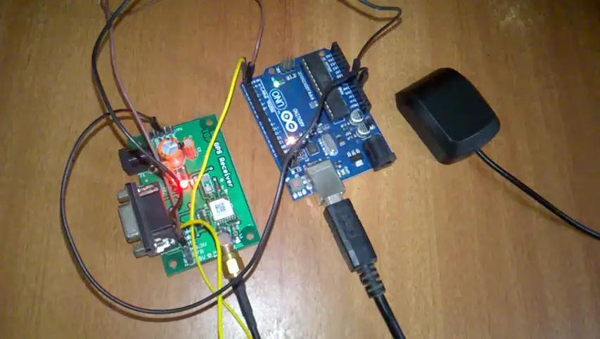
GPS module sim28ml
Here a SIMCom SIM28ML GPS Module is using to receive the GPS data. Using the module the received data can be displayed directly on any serial terminals. Hyper terminal, putty, Arduino serial monitor, etc. can be used to display the data.
To connect the module to the PC, it has to be interfaced via a USB port. The interface option available for the module would be either Rs232 or TTL or both. Use a suitable converter such as Rs232-USB or TTL-USB converter for connecting to the PC (TTL to USB converter using arduino Uno board). The module can power with a 12V DC input through a DC jack socket. Also, a +5V or +3.3V supply can use directly with the board.
Select the port connection of the device, which has listed such as COM1, COM2…COMX. Set the baud rate exactly as specified for the GPS module. The baud rate may be different for various module devices. So, it should be ensured that both the serial terminal and module has the same baud rate. Commonly the module has a baud rate of 9600bps.
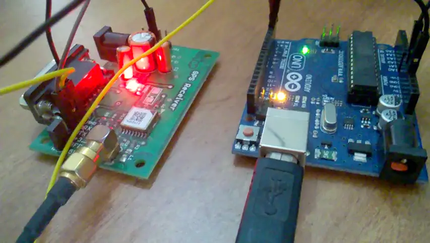
After the Power On, the module takes few minutes to receive the signal. After modem establishes a connection with the GPS, the TIMEMARK LED begins to blinks once in a second. Once the signal has received, the serial monitor display’s the GPS data in NMEA (National Marine Electronics Association standard) sentence. NMEA is a specification for communication between various marine electronic equipment.
GPS NMEA data format
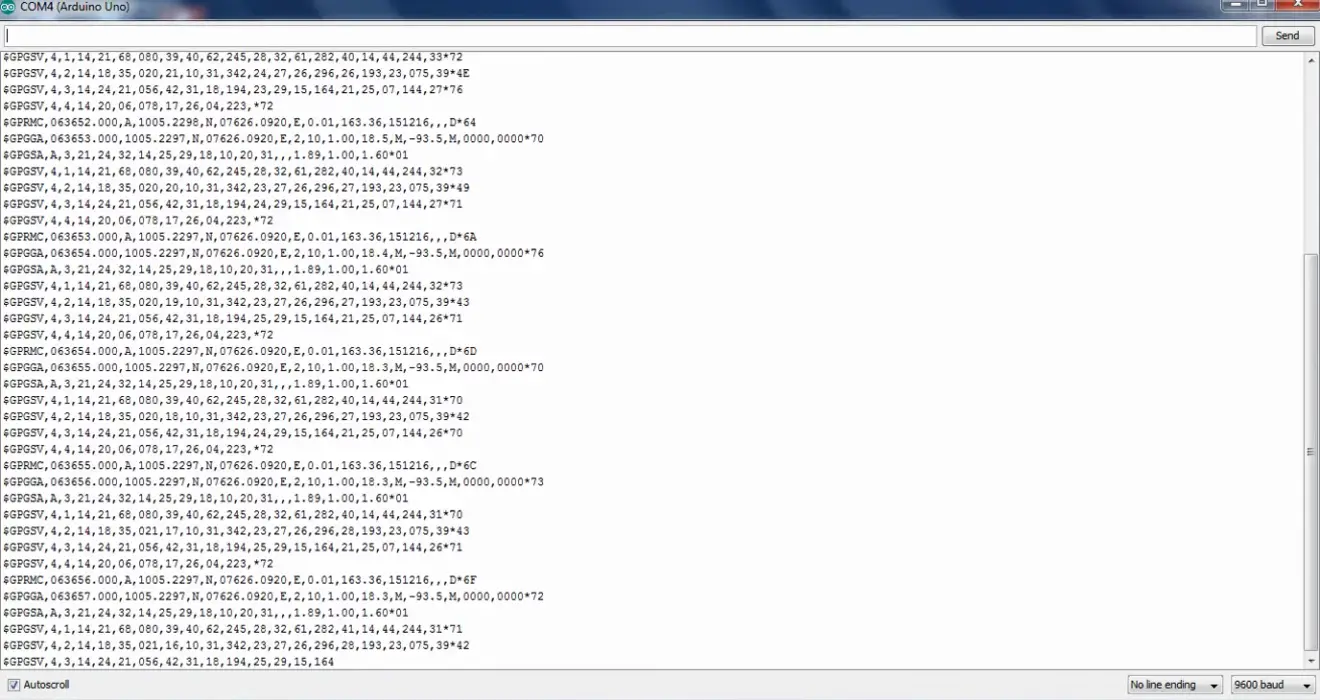
NMEA output sentence on Arduino serial monitor.
$GPRMC,062652.000,A,1005.2307,N,07626.0931,E,0.06,163.36,151216,,,A*60
$GPGGA,062653.000,1005.2304,N,07626.0930,E,1,4,5.63,24.3,M,-93.5,M,,*45
$GPGSA,A,3,21,24,32,20,,,,,,,,,5.70,5.63,0.93*0C
$GPGSV,3,1,09,21,68,066,44,32,60,271,33,18,35,016,19,39,30,261,24*76
$GPGSV,3,2,09,24,24,060,43,20,07,074,34,193,,,39,14,,,27*40
$GPGSV,3,3,09,25,,,33*77
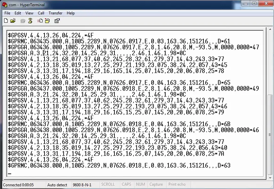 NMEA format data on hyperterminal
A direct interface to the serial monitor gives the output data in a set of lines of information, including longitude, latitude, time, date, etc.
Considering the value of latitude and longitude only.
$GPRMC,062652.000,A,1005.2307,N,07626.0931,E,0.06,163.36,151216,,,A*60
RMC Recommended Minimum sentence
$GPGGA,062653.000,1005.2304,N,07626.0930,E,1,4,5.63,24.3,M,-93.5,M,,*45
GGA Global Positioning System Fix Data
1005.230, N – Latitude is in DDMM.MMMMM format, Latitude 10 deg 05.230’N
07626.093, E – Longitude is in DDDMM.MMMMM format, Longitude 76 deg 26.093′ E
N, E, W, S represents North, East, West, and South respectively.
Get Your GPS Latitude and Longitude on screen
A direct interface to the serial monitor gives the output in the form of standard NMEA sentence, which includes many data as bulk content of lines. But, here we are extracting the Latitude and Longitude coordinate values from the NMEA standard sentence. So, this program will be more useful for those who are looking to get only the latitude and longitude from the long NMEA text.
For the Arduino coding, we are using a library function called TinyGPS, download and install it; Sketch > Include library > Add .ZIP Library.
or Sketch > Include library > Manage libraries > Search TinyGPS and install.
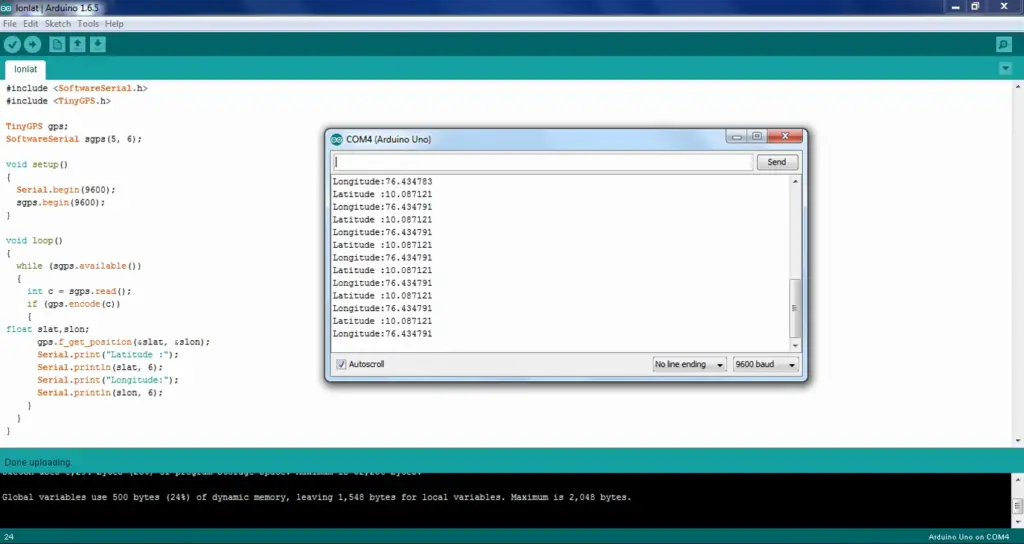
In the code, the variable “slat” and “slon” hold the coordinate values of the latitude and longitude respectively. The GPS module is interfaced with Arduino using software serial; pin 5 is defined as Receiver (RX) and pin6 as Transmitter (TX).
GPS Interfacing with Arduino Uno
| Arduino Pin | GPS Module Pin |
|---|---|
| TX (pin 6) | RX |
| Rx (pin 5) | TX |
| GND | GND |
Arduino GPS module code
#include <SoftwareSerial.h>
#include <TinyGPS.h>

TinyGPS gps;
SoftwareSerial sgps(5, 6);

void setup()
{
  Serial.begin(9600);
  sgps.begin(9600);
}

void loop()
{
  while (sgps.available())
  {
    int c = sgps.read();
    if (gps.encode(c))
    {
float slat,slon;
      gps.f_get_position(&slat, &slon);
      Serial.print("Latitude :");
      Serial.println(slat, 6);
      Serial.print("Longitude:");
      Serial.println(slon, 6);
    }
  }
}
 The world of hobby 3D printing: Can non-techies make it?
 Solving any problems: Apply this simple technique
 How to overcome Laziness: The Japanese Kaizen 1 minute method
 5 simple Tips to fall asleep early at night
Could you please put a working circuit diagram of the above connection. I am same GPS receiver that is SIM28ML, and arduino board. I am not getting any value in serial monitor.
I need help!! Please . Or can you suggest me where should I look for?
The interface of sim28ml with arduino is just a TTL interface.
Rx->Txpin6
Tx->Rxpin5
3.3v->3.3v
GND->GND
First of all make sure that your gps module is receiving data(green TMRK led flashes when GPS is fixed). Try directly to a hyper terminal or serial monitor, and check whether the module is receiving NMEA sentence data. While using with arduino, make sure that your arduino IDE has a gpstiny library function.
Bro same problem that I received that the gps doest works after twrk blinks
If the TIMEMARK LED blinks every second, it means the GPS is receiving the signal. So, you should check the communication between the GPS and the Arduino or Hyperterminal.
bro pleasee send me the code for gps sim28ml to interface with arduino
please
please
i work GPS program run success but location is not found so plzzz help me
which code have you used?
tmrk isnt blinkig at all , need help.
Timemark LED takes some time to start blinking. In indoors or under any roofing it doesn’t work fine. So try placing the antenna at different locations, mainly at outdoors and Wait for at least 3 or 5 minutes at each spot.
Thanks it works perfect! But I want latitude and longitude to be shown once on Serial Monitor… tell.me the changes on code
Replace the code inside the void loop with below code. Also intialize the int “value” at the begining as ‘0’. Here once the gps is availabe the variable “value” set to ‘1’ and afterwards the if condition always returns false, hence the latitude and longitude can print only once.
if (sgps.available() && value == 0 ) { value = 1; int c = sgps.read(); if (gps.encode(c)) { float slat, slon; gps.f_get_position(&slat, &slon); Serial.print("Latitude :"); Serial.println(slat, 6); Serial.print("Longitude:"); Serial.println(slon, 6); } }Sir I need to store the GPS latitude and longitude to a variable how can I do this by changing the code
“slat” & “slon” itself a float variable stores the latitude and longitude values respectively. Just use those variables or pass the values to another variables.
why have you taken 6 for both the slat n slon? what does it mean?
It is the number of decimal places to use. That is the number of digits to be displayed after the decimal point; here it is 6 digits.
Hello Sir, Thanks for the tutorial
However in my case the GPS module is not transmitting any value.
The TMRK LED is blinking correctly at 1 Hz. But when I upload code and use it withe my arduino mega, I get nothing on my serial monitor.
Could you help?
Thanks
Did you try connecting directly to the serial monitor, HyperTerminal, putty, etc (via TTL to USB or RS232 to USB)? Can you able to receive the data as NMEA Text?
how to connect 16*2 lcd display with this circuit
Refer Arduino LCD interface.
Hi, Anybody have the GPS code for Arduino to display all the data from the receiver.
This is the complete code to display almost all the available data in the GPS.
#include <SoftwareSerial.h> #include <TinyGPS.h> TinyGPS gps; SoftwareSerial serialgps(4,3); int year; byte month, day, hour, minute, second, hundredths; unsigned long chars; unsigned short sentences, failed_checksum; void setup() { Serial.begin(9600); serialgps.begin(9600); Serial.println(""); Serial.println("GPS Shield QuickStart Example Sketch v12"); Serial.println(" ...waiting for lock... "); Serial.println(""); } void loop() { while(serialgps.available()) { int c = serialgps.read(); if(gps.encode(c)) { float latitude, longitude; gps.f_get_position(&latitude, &longitude); Serial.print("Lat/Long: "); Serial.print(latitude,6); Serial.print(", "); Serial.println(longitude,6); gps.crack_datetime(&year,&month,&day,&hour,&minute,&second,&hundredths); Serial.print("Date: "); Serial.print(month, DEC); Serial.print("/"); Serial.print(day, DEC); Serial.print("/"); Serial.print(year); Serial.print(" Time: "); Serial.print(hour, DEC); Serial.print(":"); Serial.print(minute, DEC); Serial.print(":"); Serial.print(second, DEC); Serial.print("."); Serial.println(hundredths, DEC); Serial.print("Altitude (meters): "); Serial.println(gps.f_altitude()); Serial.print("Course (degrees): "); Serial.println(gps.f_course()); Serial.print("Speed(kmph): "); Serial.println(gps.f_speed_kmph()); Serial.print("Satellites: "); Serial.println(gps.satellites()); Serial.println(); gps.stats(&chars, &sentences, &failed_checksum); } } }output of this program
I am having a sim 900a GSM MODULE and SIM28 GPS module and an infrared sensor. I am doing a project that if any flame occurs near the sensor then the GPS location should be transmitted to a particular mobile number through GSM Module. So can you please post me the code for this project.
Refer the project : Send GPS Location Via SMS Arduino.
The above project might be the best you are looking for.
This project has a code for sending the GPS location via SMS to a mobile number by a push switch. That is when the switch has pressed the digital pin 9 gets a HIGH state input, and the Arduino send the GPS coordinates.
I think your IR flame detector has a Digital and Analog output.
If using digital just connect directly the DO to the pin 9. Whenever the DO has a high state an SMS send. The threshold can be adjusted by the pot in the sensor module.
If using with analog output connect to an analog input pin and change the same “if” condition so as to check whether the input value reaches above the threshold, and send an SMS whenever the value rises above the threshold.
I have SIM 900A MINI V3.8.2. I don’t know the connection for this module using Arduino UNO. Please send me the connection pins and diagram as well as the code to send SMS and my GSM module is does not searching signals even though our area receives 4G Signals and you please give us the solutions.
Refer: Arduino GSM Interface and working.
we find difficult to build a system that detect and report the accident location and sending via sms
here we use GPS sim28 and GSM sim 900a acclerometer adxl 335 and piezo elecrtic sensors
coul you please send us the code for the system
You can build it by few modifications in the code @, refer: Arduino Send GPS Coordinates via GSM.
the code which u posted is working only in arduino uno only. To get output in arduino mega what has to be done
“Not all pins on the Mega and Mega 2560 support…”. Refer https://www.arduino.cc/en/Reference/softwareSerial.
The GPS module is not transmitting any value. The TMRK LED is blinking correctly. But when I upload code it gives error message .Plz help me..
What was the error message?
i am using gps sim28ml module and arduino uno. I had uploaded the same code with given circuit connection but tmrk light on the gps is not blinking at all.
Please help.
If the TMRK LED is not blinking it means the GPS is not getting any data. Sometimes it takes a few minutes to start blinking. Try adjusting the antenna of the module. It is recommended to place outdoor, open roof or at least near to the window because GPS receivers require a line of sight to fix their position.
I am using sim28 ml and aurdino uno .tmrk light is not blinking at all .I tried keeping it outdoor but still no use.Please help
Try another module. Try at some distant location.
i have used library ting gps downloaded from
https://github.com/mikalhart/TinyGPS
this website
the gps shows the same location at every where we did not provide same in buit values but sam gps value is printed every where even in different places
give me a solution to tracking
Did you wait a few minutes at new location points? The module needs some time at each location to pick up new coordinates. Try another library.
Try directly to receive data in NMEA format without the library and check whether the coordinates at the line “$GPGGA,0…” are changing with location.
i waited more than 30 min but it showed the same location in different places
could you give steps how to receive data in NMEA format without the library ?
It is briefed in the first few paragraphs of this article about connecting GPS module using TTL to USB converter and view data through putty, Arduino serial monitor or Hyper terminal.
How to store the slat value in a variable up to 6 decimal points…?
“slat” itself a variable which stores up to 6 decimal points. If you need to transfer to another variable just add ” float variable1; Variable1=slat;”.
hi sir i’m working on vehicle tracking system and i want to send the GPS coordinate to the website i created how can i do that
You have to create a web server using Ethernet Shield and Arduino board. And request the value from the ip of the server to the website.
i was trying to work simulation in proteus using raspberry pi 3 and i want to with script pyhton code rather than the flow chart. how can i load the script code to the raspberry if it’s possible?
K⸮⸮⸮z⸮I⸮⸮j
$GPGLL,,,,,001455.261,V,N*7A
$GPGSA,A,1,,,,,,,,,,,,,,,
hello Sir,
I uploaded everything properly this is being displayed on my serial monitor. what is it? I can’t understand anything coz it is not showing latitude and long.
Sir i am using sim800A gsm gps module and i m getting the message or call through gsm but not recieving any latitude and longitude data.
This could be a communication issue with the GPS receiver. Connect the GPS module separately and display it in the serial monitor to check whether it is receiving the signal.
WORKING PERFECTLY
THANK U FOR YOUR CODE
IT WILL take more than 10 minutes to blink LED
AFTER THAT it gives correct result
thank u sir
Hi Admin,
Its a great tutorial on GPS data in NMEA format with pictures which gave me basic knowledge on coding as well as Arduino as I’m new to both. Before going to further let me tell you about me, basically I’m a Marine Electronics Engineer mainly deals with marine GPS installation and data in NMEA format interfacing with other marine devices. Coming to my project, I would like to design a device which displays “GPS Course” using 5 digit 7sigment display and Arduino interfacing marine shipborn GPS (of Different makes). For example, referring to the picture “NMEA format data on hyperterminal” in above tutorial, considering ‘$GPRMC’ (Recommended Minimum Coordinates) sentence, 163.36 represents GPS Course in degrees. My aim is to display the course 163.36 or 163.3 deg.
I request you to assist me in choosing the libraries and code as well as hardware shields required as the all marine GPS data is in RS422 protocol.
Thanks In Advance.
Which model GPS module you are using?
I’m using FURUNO GPS model:GP-39 which gives output data NMEA in RS422.
You can use an RS422 to TTL converter to interface with Arduino using the inbuilt SoftwareSerial library.
My project is tracking alzheimer’s patient position using arduino nano, gps and gsm, if the patient is outside the safezone send the caregiver an alert i need the code please
Refer https://mechatrofice.com/arduino/send-gps-location-via-sms; here the condition to send SMS can be replaced with another condition to compare the difference between the known longitude and latitude value (center of the safe zone) with the current GPS values.
The safe zone can be obtained by taking the latitude and longitude values of the center location (home/room/etc..) and the allowed difference from the current value.
Thank you..
I have another question please, how can i determine the safe zone on the map?
You have to pick the GPS coordinates from the map to determine the safe zone.
For a direct interface with the map, you need maps-API and Arduino internet connectivity.
Hmmm, maps-API is not for free, and here in our country sudan we can’t pay for this, is the any idea to determine the save zone? Help me please
You have to manually take the GPS coordinates at the center point. Then compare this value with the instantaneous value from the GPS receiver.
Like GPS device current distance from the center can be calculated as, D = √((y2-y1)^2 + (x2-x1)^2); a simple way where x2,y2 current coordinates and x1,y1 center coordinates. Or using a formula to find the distance between two latitude and longitude values. Use this distance value to compare with the radius of the safe zone.
Hi,
I have a USB to TTL converter which I want to use instead of Arduino Uno.
Will this modifications work?
Serial.print(“Latitude :”);
Serial.println(slat);
Serial.print(“Longitude:”);
Serial.println(slon);
USB to TTL converter can be used to connect the Arduino to PC via TX/RX pins; useful for connecting Arduino boards without a USB port. But still, need an Arduino microcontroller board for this code to work.
Why you’ve added that Jumper to BFR and +5v pins ???????
thanks! for such a informative blog!
bro iam using gps neo 6m module ,DO i have to change the code ,where should i change