LED Flasher Circuits Using 555 Timer IC
IC 555 Simple LED Flasher
An LED flasher circuit can be used as an LED blinker, vehicle indicator light, signal flashlight, etc. A simple blinking circuit is basically a circuit to continuously ON and OFF the light supply on a fixed time interval. That is a periodic output of HIGH and LOW state sequences that ON and OFF the LED repeatedly.
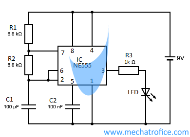
Here circuit consists of an astable multivibrator using an NE555 timer IC, which generates a square wave. The circuit has an approximate ON state time of 0.94 Seconds and OFF state time of 0.47 Seconds.
The Rate of flashing of the circuit can be calculated as,
Ton = 0.69*(R1 + R2)*C | Toff = 0.69*R2*C
Ttotal = Ton + Toff = 0.69*(R1 + 2*R2)*C
The flashing rate can be adjusted by varying the values of either resistors R1 or R2 or the capacitor C1. Also, instead of using a fixed resistance value for R1 and R2, either one of the resistance can be replaced with a potentiometer. Then the rate of flash can easily be tuned
components required
IC – NE555
Resistor – R1, R2 – 6.8k, R3 – 1k
Capacitor – C1 – 100uf, C2 – 100nf
LED -Red
Supply – 9v battery
Alternating LED Flasher With 555 IC Circuit Diagram
This alternate LED flasher consists of a pair of LEDs that blink alternately. It has the same circuit as a simple LED flasher circuit using a 555 astable multivibrator. The only difference is that one more LED is added in the circuit, which ON when the 555 output is in a low state.
In the circuit, LED1 lights when the output pin has a LOW state, and LED2 lights when the output is in a HIGH state.
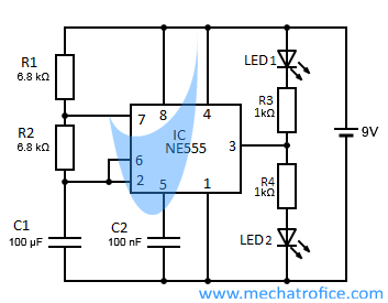
The rate of flashing can be adjusted by varying the ON period and OFF period of the astable multivibrator.
components required
IC – NE555
Resistor – R1, R2 – 6.8k, R3,R4 – 1k
Capacitor – C1 – 100uf, C2 – 100nf
LED – 2 Nos
Supply – 9v battery
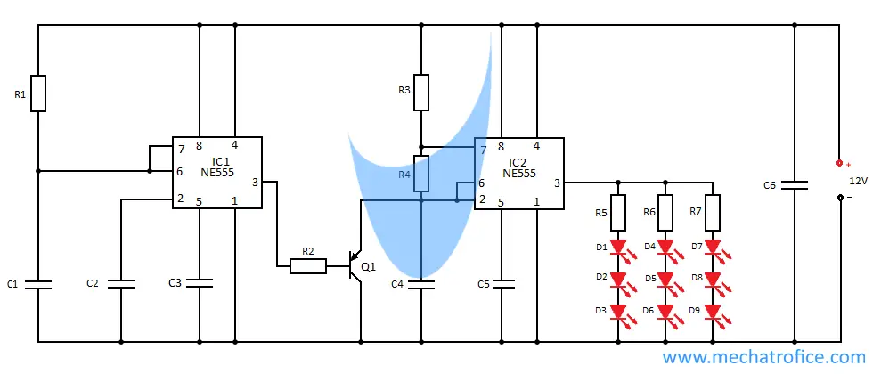
Police Flashing Strobe Light Circuit Using 555
Strobe lights are commonly used as emergency vehicle lights for visual warnings. Their light effects are similar to the flashing light in police vehicles, ambulance, beacon light bars, etc.
The given police light circuit consists of two 555 astable multivibrators. One with a lower oscillation frequency (IC1 multivibrator section) and the other with a higher frequency (IC2 multivibrator section).
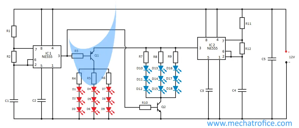
The IC2 consists of a simple LED flasher circuit, which continuously flashes the LED. And using the signal from the low-frequency multivibrator, the signals from the IC2 are alternately switched to the RED and BLUE LEDs. Here the LED set consists of 3×3 Red and 3X3 blue LEDs.
The square wave output of IC2 is connected to the RED and BLUE LEDs through an NPN transistor Q1-BC547 and a PNP transistor Q2-BC557.
The base of both transistors is biased from the output of the low-frequency multivibrator. So it switches the transistor Q1 and Q2 alternatively with the high and low state at the output.
On the high output state of IC1, the Q2 switches to forward active mode and drives the flashing signals to BLUE LEDs. Similarly, in the low output state of IC2, the Q1 drives the signals to the RED LEDs.
The rate of flashing of LED sets and switching time between the LED sets can be adjusted by varying the time period of the two multivibrator circuits.
Components required
Integrated circuit – IC1,IC2 – NE555
Transistor – Q1 – BC557, Q2 – BC547
Resistor – R1, R3, R10, R11 – 1K, R2 – 470K, R4-R9- 220ohms, R12- 100K
Capacitor – C1,C4 – 2.2uf, C2,C3 – 0.01uf, C5 – 220uf
Diode – D1 – D9 – Red LED, D10 – D18 – Green LED
Simple Flashing brake light Circuit
The circuit can use to make a simple pulsating stop brake light which continuously flashes as long as the brake is applied. Here we are using a 555 astable multivibrator to generate the flashing. The working of the flash brake light circuit is the same as the simple 555 flasher circuit. With the given values for R1, R2, and C1, the circuit has an ON period and OFF period of 0.125 seconds and 0.124 seconds respectively.
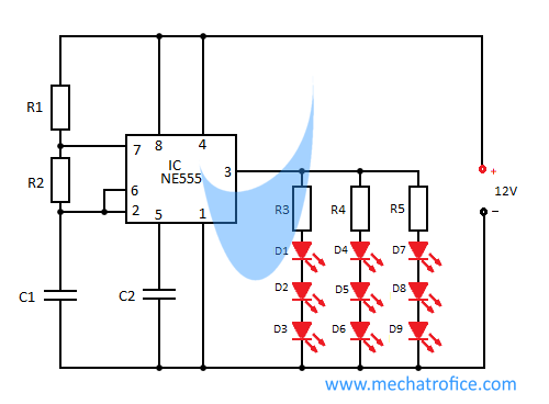
The LED brake light has a set of 3×3 LED bulbs, 3 parallel sets of 3 series LEDs, and 220 ohms resistance. The 555 IC has a maximum output current of 200mA. The output current driven by an LED is about 20ma – 40 ma. Here in the set, it is about 25ma. As the total current is below 100ma, the LEDs can be connected directly to the output pin of the 555IC. Also, as the brake light is not lighting for too long the IC does not heat as much. Even though, the circuit can work fine if it kept ON for a long period.
The switch should be placed so as to activate the circuit while applying the brake. Or replace the switch with any other easy mechanism that makes an electrical contact during braking. Also, the circuit can be connected in parallel to the existing brake light. But the power rating of the wire and fuse should be considered while connecting along with it.
Flash Light – Components required
Integrated circuit – IC – NE555
Resistor – R1 – 1K,R2 – 82K, R3,R4,R5- 220ohms
Capacitor – C1 – 2.2uf, C2 – 0.01uf
Diode – D1 – D9 – Red LED
Flash and Hold Brake light Circuit
In the flash and hold circuit, the light does not flash continuously as like a normal flasher. Instead, the circuit flashes initially for a few seconds and then hold the ON state until the brake switch is released.
This brake light circuit consists of an additional monostable multivibrator with the above flasher circuit. In the circuit, the output of the monostable multivibrator is connected to the base of a PNP transistor, which is connected across the capacitor C4. So, during the high state of the IC1, the Q1 is OFF. Thus the astable multivibrator generates periodic signals, which flash the LEDs. After the quasi-state period of IC1, the output return to the low state. At this time the Q1 ON and it shunts the capacitor. Thus the voltage at the trigger pin becomes below 1/3Vcc and holds the ON state at the output of IC2, which is actually interrupting the working of the astable multivibrator.
The flashing time of the circuit is equal to the time period of the monostable multivibrator. So the period of flashing can be adjusted by varying the time period of the monostable multivibrator.
Brake Light – Components required
Integrated circuit – IC1,IC2 – NE555
Transistor – Q1 -BC557
Resistor – R1 – 470K, R2,R3 – 1K, R4 – 100K, R5-R7- 220ohms
Capacitor – C1 – 4.7uf, C2 – 22pf, C3,C5 – 0.01uf, C4 – 2.2uf, C6 – 220uf
Diode – D1 – D9 – Red LED
 The world of hobby 3D printing: Can non-techies make it?
 Solving any problems: Apply this simple technique
 How to overcome Laziness: The Japanese Kaizen 1 minute method
 5 simple Tips to fall asleep early at night

Those are some good circuits. Do you have anything on an alternating two light LED that uses 24vdc? I only have 24vdc to work with in my installation.
Thank You
Tony Wiser
An easy method is, you can add an LM317 voltage regulator to the circuit to reduce the 24V supply to 12V.
Refer: https://mechatrofice.com/circuits/battery-charger-circuit ( You just need to refer only the LM317 regulator section inside the circuit.)
Hi! I try to make the Flash and Hold Brake light Circuit with the diference that I dont put anything in the pin 3 of the IC2. I just test with a voltimeter and dont have tension in these pin.
Then I test the power supply disconected and have 12,8v. Next I connect the power supply and test his tension (connected to the circuit) and have 0,08v.
Whats could be wrong?
Sorry for my english and thank you.
It might be some connection issue. Check the IC1 and IC2 sections separately, output 3 of both IC1 and IC2. Also, the voltages at pins.
Better try with LEDs at pin 3, because the output is a pulsating signal.
It was indeed a bad connection. One of the electrolytic capacitors was poorly connected.
The circuit worked perfect, except that I modified some resistors and capacitors to leave it to my liking.
Thank you
How to make police flasher light with two 555 timer and no transistor