Audio Tone generator circuit using 555, 741 IC
A tone generator circuit can be used for various applications such as alarms, bells, indicators, etc. A tone generator consists of a square, triangle, sawtooth periodic wave generator circuits, commonly square wave generators. Such periodic signals produce a beeping sound when connected to audio transducers such as a speaker, piezo, etc.
Simple Tone generator circuit using 555
The below circuit consists of an astable multivibrator using a 555 timer IC. It generates a continuous square wave output. The circuit has an oscillation frequency about 670-680 HZ. The audio frequency of the circuit can be changed to wide ranges by varying the values of any of the resistance R1, R2 or the capacitance C1.
To calculate the resultant frequency from the values of R1, R2, C1,
The frequency, f = 1 / (0.69*(R1 + 2*R2)*C)
For frequent tuning, it’s better to replace the resistance R2 with a potentiometer. In the position of R2, connect the wiper terminal and either one of the end terminals of the pot.
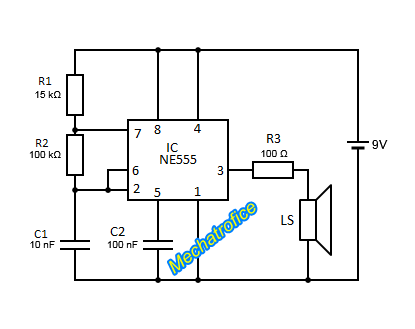
Choose a Loudspeaker with appropriate impedance and power, an ordinary 8 ohms Loudspeaker can work fine. The output resistance should be adjusted with the power rating of the selected Loudspeaker.
To improve the output quality, amplify the output signal using a transistor. The circuit can perform well even without amplification.
components required
IC – NE555
Resistor – R1 – 15k, R2 – 100k, R3 – 100
Capacitor – C1 – 10nf, C2 – 100nf
Loudspeaker
Supply – 9v battery
Op amp tone generator circuit
This circuit is a tone generator using an op amp. Here also the circuit is an astable multivibrator which generates a square wave signal around 3KHZ frequency.

The 741 op amp can deliver only a small output current. So, if it has connected directly to a speaker, the generated sound will not have enough volume. Thus, the output signal has amplified using a transistor.
Astable multivibrator of an op amp will contain both positive and negative half cycle. But here the emitter of the transistor is connected to the negative of the supply. So it only contains 6V for high state output. And a 0V for low state or during the negative half cycle.
The capacitor C1 and R3 have connected to signal ground or Equipotential. If the supply is taken from a single supply unit, the equipotential for the supply can be obtained from a voltage divider network. Or by using two series battery or supply, a reference node can take as signal ground or zero volts.
components required
IC- 741
Resistor – R1 – 15k, R2,R3 – 10k, R4 – 3.3k
Capacitor – C1 – .01uf
Transistor -Q1 – BC547
LS – Loudspeaker
Police siren circuit using NE555
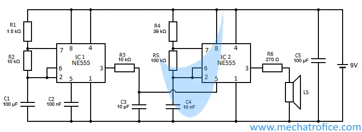
The wailing siren can be used as a tone generator, indicators, alarm, etc.
Components required
IC1,IC2 – NE555
Resistor – R1 – 1.5K, R2, R3 – 10k, R4 – 39k, R5 – 100k, R6 – 270
Capacitor – C1,C5 – 100uf, C2 – 100nf, C3 – 10uf, C4 – 10nf
Loudspeaker
Supply – 4.5V -16V
Beeper circuit using 555 timer IC
Here the circuit for a simple Beeper alarm using 555 IC, which generates a Beep-Beep tone. This tone generator circuit is suitable for indicators, emergency alarms, etc. The circuit consists of two astable multivibrator circuits, one with a very low oscillation frequency and the other with a high-frequency tone.
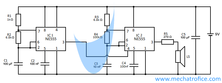 In the given circuit, the multivibrator section IC1 and IC2 has an oscillation frequency about 1HZ and 700HZ respectively.
The IC2 section consists of a simple tone generator circuit. If we connect the reset pin of the IC2 to the supply, then it works as a normal tone generator. But here the output pin 3 of the IC1 has connected to the reset pin 4 of the IC2. So, the low frequency signal interrupts the oscillation of high frequency signal.
As the 555 IC has an active low input reset, the tone generator section of the circuit oscillates only during the high state of the output of IC1 . Thus the circuit ON and OFF the high-frequency audio signal between a short interval of time, which results in a beep – beep sound.
The output tone can be widely varied by adjusting the frequency of the first and second multivibrators.
components required
IC1,IC2 – NE555
Resistor – R1 – 1k, R2, R3 – 6.8k, R4 – 100k, R5 – 270
Capacitor – C1,C5 – 100uF, C3 -10nF, C2,C4 -100nF
LS – Loudspeaker
Supply 9V DC
 The world of hobby 3D printing: Can non-techies make it?
 Solving any problems: Apply this simple technique
 How to overcome Laziness: The Japanese Kaizen 1 minute method
 5 simple Tips to fall asleep early at night
Do you have any video of that? I’d like to find out some additional information.
I have no videos, what information do you need?
Would like to hear physically the sounds generated by each circuit .