Vibration sensor alarm circuit diagram
The circuit can be used as an intrusion detector alarm which can be simply placed on doors, floors or any surface where any vibration or pressure is generated during any intrusive actions. This burglar alarm works by detecting vibrations produced in a burglary attempt. The circuit mainly uses a piezoelectric sensor to sense the vibrations. A piezoelectric sensor is a device that generates electrical energy or induces a voltage from a force, pressure or any physical energy. In the circuit, the piezo sensor is connected to the trigger pin2 of IC7555; the IC triggers when the voltage at pin 2 drops below 1/3Vcc of the supply voltage. On inducing a voltage across the sensor terminals, it can produce a voltage drop at pin 2 which can trigger the IC. Then the output at pin 3 switches to a high state and the buzzer gets ON.
The threshold pin 6 is connected to the negative terminal; the output OFFs when threshold pin voltage reaches 2/3Vcc of the supply voltage. Thus, once the circuit has triggered, the IC remains at ON state until the circuit resets by closing switch S1, which sets the pin 4 (IC 555 has an active low reset) to an active low state.
components required
IC1 – 7555
Piezoelectric sensor
Resistor – R1 – 1M, R2 – 1k
Capacitor – C1 – 100nf
Buzzer
Switch – S1-SPST
Battery-6V
 The world of hobby 3D printing: Can non-techies make it?
 Solving any problems: Apply this simple technique
 How to overcome Laziness: The Japanese Kaizen 1 minute method
 5 simple Tips to fall asleep early at night
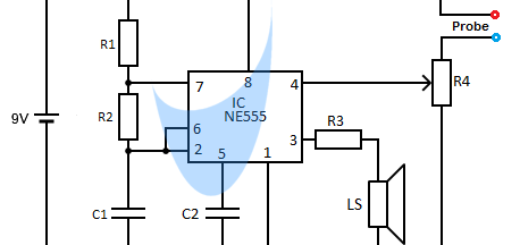


does this circuit require arduino?
Not at all, the circuit requires no code or microcontrollers. Its main components are just a 7555 IC and a piezoelectric sensor.