Battery charger circuit with indicator, over current & overcharge protection
LM317 battery charger with overcurrent protection circuit
The circuit is a 6V LM317 voltage and current control battery charger circuit which generates a regulated 6V DC output.
The transformer T1 steps down the input 230V/50HZ AC supply to a 6V AC. Then it converted to a 6V DC, by a bridge rectifier circuit. The capacitor C1 filters the rectified output.
The circuit uses an LM317 regulator, which is an adjustable linear positive voltage regulator which can operate in an input voltage range of 3-40V.
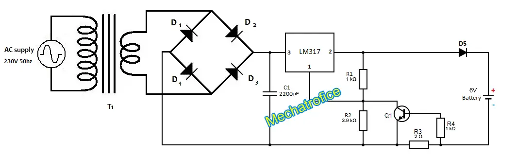
The value of resistor R1 and R2 determines the output voltage value of LM317.
Equation for LM317 output voltage, Vout = 1.25 * (1+ R2/R1)
In the given circuit, the resistor combination (R1 & R2) will obtain a maximum output voltage of 6.125 volts.
The LM317 has a maximum operating current of 1.5 Amperes, with an internal current limiting and thermal overload protection. But, the circuit is already designed with an additional overcurrent protection. Current limiting arrangement regulates the output voltage of the LM317 to limit the current flow above a fixed value. The input voltage to the battery will be adjusted itself, with respect to the charging current. The output voltage of the circuit varies from 1.25V to 6.125 V. When the current flow through the sensing resistor R3 increases, the base current of the Q1 also increases. So it will reduce the resistance across R2 and thereby the value of Vout.
This circuit is designed for charging 6V 4.5AH lead acid batteries. But the output voltage and current limit of the circuit can be varied to use with other batteries. The charging voltage and current depends on the value of resistance R2 and R3 respectively. Thus, by replacing the resistance R2 and R3 with a potentiometer we can always adjust the output voltage and current of the circuit.
But, while using the circuit with other batteries, the charging rate and other parameters should be considered.
Components required
LM317 – Voltage Regulator IC
Resistor – R1, R4 – 1k, R2 – 3.9k, R3 – 2 ohms
Capacitor – C1 – 2200uf
Diode – D1-D5 -1N4007
Transistor – Q1- BC547
Transformer – T1- 230V/6V,1A
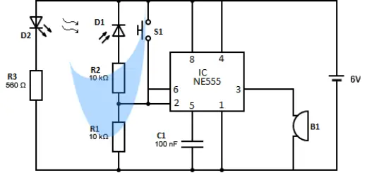
Automatic battery charger with LED indicator and Overcharge protection circuit
Here the circuit for a 6V automatic battery charger circuit with overcharge protection, LED charging indicator and current limiting feature.
The circuit controls the charging of the battery by taking feedback of the voltage across the battery terminals. The circuit charges the battery as far as it has a voltage below the threshold limit. And if it reaches a value equal to the threshold, the circuit automatically cut OFF the supply from the battery.
The LED D1 and D2 indicate the status, whether the battery is charging or not. The red light (D2 LED) indicates the battery is charging and the green light (D1 LED) indicates that the battery has fully charged.
The battery charger circuit can work with a wide range of input DC supply voltages. The circuit can operate in the range of voltages approximately above 6.2V and up to a maximum 18V (Maximum operating voltage of IC7555).
Circuit Operation
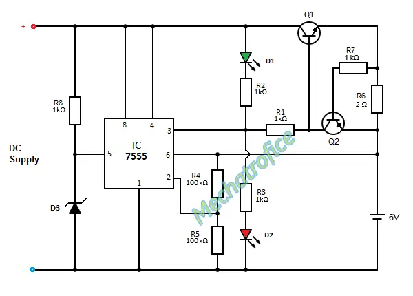
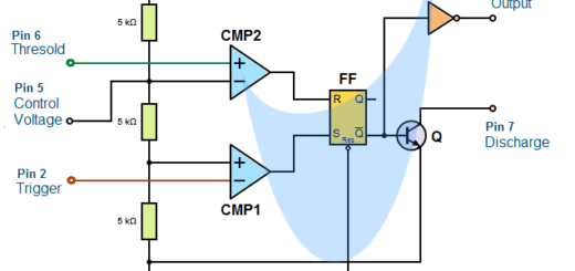
Normally a 555 IC has a threshold and trigger voltage of 2/3 and 1/3 of the supply voltages respectively.
Here the zener diode 1N4735 of 6.2V has connected to the control voltage terminal (pin 5) as shown in the circuit. The trigger input (pin2) has connected through a voltage divider network and threshold input (pin6) has connected directly from the battery. This adjusts the threshold voltage and trigger voltage to a fixed value of 6.2V and 3.1V, for any input voltage values above 6.2V.
The output (pin 3) of the 7555 is connected to the base of the transistor Q1, which controls the charging current of the battery. When the voltage of the battery goes below 6.2V, the trigger input at pin2 becomes 3.1V. Then the output switches to the high state and ON the transistor Q1. Similarly, when the voltage reaches the threshold value 6.2V the output turns to the low state and OFF the Q1.
The arrangement with transistor Q1 and Q2 works as a current limiter circuit. When the current flow to the battery increases, it proportionally increases the voltage drop across the current sense resistor R6 also. Thereby, the base current of transistor Q1 pulled down by the transistor Q2 and reduces the collector current through the Q1. So, the circuit can able to limit any chance of overcurrent.
Components required
Integrated circuit -IC1 – 7555
Resistor – R1,R2,R3,R7,R8 – 1K, R4, R5 – 100K
Diode – D1 – Green LED, D2 – Red LED, D3 – Zener 1N4735
Transistor – Q1 – 2N2222, Q2 – BC547
 The world of hobby 3D printing: Can non-techies make it?
 Solving any problems: Apply this simple technique
 How to overcome Laziness: The Japanese Kaizen 1 minute method
 5 simple Tips to fall asleep early at night
how much voltage is of C1 capacitor?
16V or 25V, any value above 8.5 Volts.
what is the range of current & voltage around R2 & R3 respectively during at 6v 4.5 Ah battery charging in lm317 circuit?
The instantaneous charging current and output voltage value varies with respect to the voltage level of the battery. The maximum charging current is around 350mA. R2 voltage range 0 to 4.87V, R3 current 0 to 350mA.
the diagram is not showing on my browser
Ensure that images are not being blocked in browser settings.
മുകളിൽ പറഞ്ഞിരിക്കുന്ന മെറ്റീരിയൽ ലിസ്റ്റിൽ 230V/6v,1A ട്രാൻസ്ഫോർമർ ആണ് ഉപയോഗിച്ചിരിക്കുന്നത് അതിനുപകരം 230V/0-9V, 500mA ട്രാൻസ്ഫോർമർ ഉപയോഗിച്ചാൽ എന്തെങ്കിലും പ്രശ്നം ഉണ്ടോ…?
Google Translate: In the above material list has been used a 230V/6v,1A Transformer, instead of that is there any problem with using 230V / 0-9V 500mA transformer?
No problem, you can use a 230V / 0-9V 500mA transformer. The circuit can adjust it with the current resistor values it has.
Google Translate: പ്രശ്നമില്ല, നിങ്ങൾക്ക് 230V / 0-9V 500mA ട്രാൻസ്ഫോർഡർ ഉപയോഗിക്കാം. സർക്യൂട്ട് അതിനെ നിലവിലുള്ള റെസിസ്റ്റർ മൂല്യങ്ങളാൽ തന്നെ ക്രമീകരിക്കും.
Can I charge 7.2V Li battery of camera? Camera charger gives output of 8.4V.
I have adjusted output of 8.4 V with the zener diode, but both LEDs are always ON when I start charging.
Even both the LEDs are always ON, you just need to check about the output voltage and to make sure it is not exceeding.
The resistor values all are designed to operate with a 6V output, so you have to adjust the resistor values also. Hence, the charging current of the battery, etc need to be considered; maximum charging current depends on the value of resistance R6.
In the case of LED, try adding the series resistance value to minimize the current through LED during normal operation.
Can I Charge 6V 1.2 AH Sealed Lead Acid battery with this circuit (first circuit)
Yes, you can.
I have 12v 500mA Transformer…..Can i charge 12v 6Ah lead acid battery
Yes, you can. But you have to adjust the output voltage by varying the component values; as briefed in the article.
what do i change to make it a 4v charger
For the LM317 circuit,
Vout = 1.25 * (1+ R2/R1)
4 = 1.25 * (1 + R2/R1)
R2 = 2.2 * R1
Take R1 = 1Kohms
R2 = 2.2Kohms
For a 4V output change resistor R2 with a 2.2kohms resistor.
hello many thanks for your upload i tried it and it work perfectly well.o/p voltage was 6.06v i used 2.2Ohms for R3
Please how can i include indicator in the circuit?on and full charged
For exact indication you have to use a comparator circuit with a zener reference voltage, similar to https://mechatrofice.com/circuits/voltage-level-indicator-circuit.
You also manage your requirement with a basic arrangement also.
Circuit B is a simple arrangement just using a 3V zener with a 3V LED. Connect the circuit across the battery; Terminal 1 at +ve and 2 at -ve. So as to light the LED only for a voltage around 6V, you can set it more precisely by selecting the value of resistor R1(Depends on the minimum current & voltage of your LED). For example if the LEDs minimum voltage is 2 and minimum current is 5ma, then a 6V is required to ON the led for an R1 of 200ohms.
6V-3V-2V = 1V, 1/5ma = 200ohms; 200 ohms is an approximate value you have adjust it, try with a resistor near to this value or use a potentiometer to set resistance R1.
In Circuit A connect the 2 & 3 across the battery in +ve and -ve terminals respectively, 1 to the output pin 2 of Lm317. As a rule of thumb you can select R1 as 1k and R2 as 100ohm, then try adjusting the values to get exact ON/OFF of the LED.
For an ON indicator you can connect an LED with appropriate resistor across the capacitor C1.
many thanks for your prompt response will try it and give you feedback as usual
You are welcome
Can I use 9-0-9 v transformer
Yes, you can use a 9V(9-0)transformer because the LM317 has an input voltage range around 1.2 V to 37 V. But the power dissipation increases compare to a 6V transformer due to a 3V(9-6V) drop.
hello, I want to design this ‘Automatic battery charger with LED indicator and Overcharge protection circuit’ to charge a 3V battery, what changes are required in it? kindly reply
Change the Zener diode D3 with a 3V zener or above (closest to 3V).
How the sensing resistor works as two ends of it is connected to the ground ? And as battery initially charges, the current will be high and so the sensing resistor as per the description reduces the out voltage. So will the battery attain full charge ever?? Pls reply
You are referring to the circuit of “LM317 battery charger with overcurrent protection circuit” and resistor R3 in the circuit.
Two ends of the R3 are not connected to the ground, the charging current of the battery flows through R3 to the negative terminal of the rectifier output.
Initially, the charging current will be high if it is connected directly, the R3 is to limit that current by reducing the output voltage. So the voltage will be always regulated so as to limit the excess current. As the battery charges, the voltage across the battery increases, and the voltage across R3 decreases, thereby the output voltage increases.
how to modify this circuit to charge 12v7.2Ah?
Can i use 12v 2ah AC-DC adapter?
THANKS